2016 BMW M2 turn signal
[x] Cancel search: turn signalPage 95 of 220

E.g. the sensors are unable to detect fog or
hazy weather. To avoid safety risks under
these conditions, you should always switch on
the lights manually.
Daytime running lights General information
Position of switch:
, ,
The daytime running lights light up when the
ignition is switched on. After the ignition is
switched off, the parking lights light up in posi‐
tion
.
Activating/deactivating In some countries, daytime running lights are
mandatory, so it may not be possible to deacti‐
vate the daytime running lights.
On the Control Display:
1."Settings"2."Lighting"3."Daytime running lamps"
Settings are stored for the profile currently
used.
Adaptive Light Control
The concept Adaptive Light Control is a variable headlight
control system that enables dynamic illumina‐
tion of the road surface.
General information
Depending on the steering angle and other pa‐
rameters, the light from the headlamp follows
the course of the road.
To avoid blinding oncoming traffic, the Adap‐
tive Light Control does not swivel to the driv‐
er's side when the vehicle is at a standstill.
Depending on the equipment version, Adap‐
tive Light Control consists of one or several
systems:▷Cornering light, refer to page 95.
Activating
Position of switch
with the ignition
switched on.
Cornering lights
The cornering lights are automatically
switched on depending on the steering angle
or the use of turn signals.
When driving in reverse, the cornering lights
may be automatically switched on regardless
of the steering angle.
Malfunction
A Check Control message is displayed.
Adaptive Light Control is malfunctioning or has
failed. Have the system immediately checked
by a dealer’s service center or another quali‐
fied service center or repair shop.
High-beam Assistant
The concept The high-beam Assistant detects other traffic
participants early on and automatically
switches the high beams on or off depending
on the traffic situation. The assistant ensures
that the high beams are switched on, when‐
ever the traffic situation allows. In the low
speed range, the high beams are not switched
on by the system.
General information The system responds to light from oncoming
traffic and traffic driving ahead of you, and to
adequate illumination, for example, in towns
and cities.
The driver can intervene at any time and switch
the high beams on and off as usual.
Seite 95LightsControls95
Online Edition for Part no. 01 40 2 970 518 - II/16
Page 96 of 220
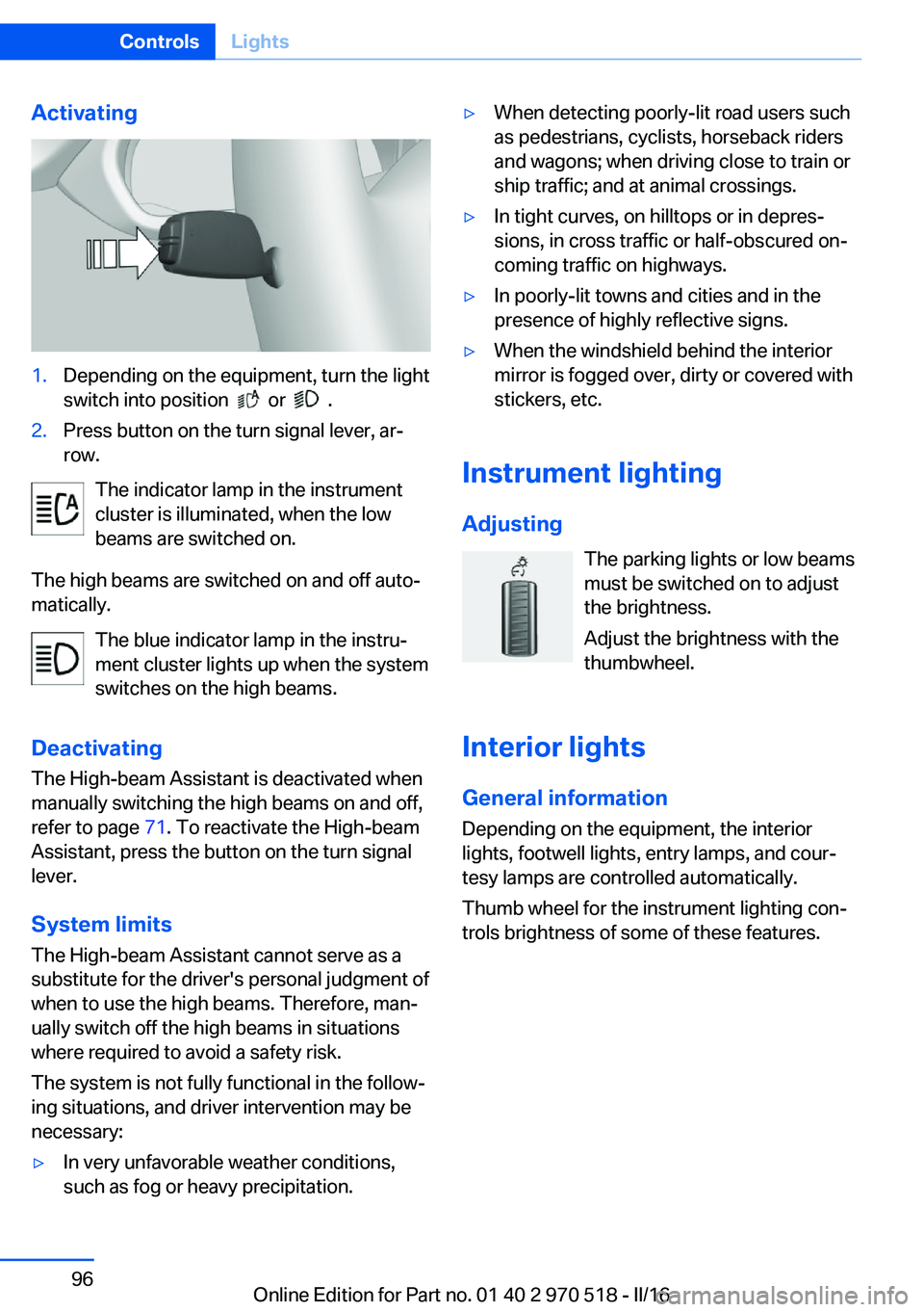
Activating1.Depending on the equipment, turn the light
switch into position
or .
2.Press button on the turn signal lever, ar‐
row.
The indicator lamp in the instrument
cluster is illuminated, when the low
beams are switched on.
The high beams are switched on and off auto‐
matically.
The blue indicator lamp in the instru‐
ment cluster lights up when the system
switches on the high beams.
Deactivating The High-beam Assistant is deactivated when
manually switching the high beams on and off,
refer to page 71. To reactivate the High-beam
Assistant, press the button on the turn signal
lever.
System limits
The High-beam Assistant cannot serve as a
substitute for the driver's personal judgment of
when to use the high beams. Therefore, man‐
ually switch off the high beams in situations
where required to avoid a safety risk.
The system is not fully functional in the follow‐
ing situations, and driver intervention may be
necessary:
▷In very unfavorable weather conditions,
such as fog or heavy precipitation.▷When detecting poorly-lit road users such
as pedestrians, cyclists, horseback riders
and wagons; when driving close to train or
ship traffic; and at animal crossings.▷In tight curves, on hilltops or in depres‐
sions, in cross traffic or half-obscured on‐
coming traffic on highways.▷In poorly-lit towns and cities and in the
presence of highly reflective signs.▷When the windshield behind the interior
mirror is fogged over, dirty or covered with
stickers, etc.
Instrument lighting
Adjusting The parking lights or low beams
must be switched on to adjust
the brightness.
Adjust the brightness with the
thumbwheel.
Interior lights
General information
Depending on the equipment, the interior
lights, footwell lights, entry lamps, and cour‐
tesy lamps are controlled automatically.
Thumb wheel for the instrument lighting con‐
trols brightness of some of these features.
Seite 96ControlsLights96
Online Edition for Part no. 01 40 2 970 518 - II/16
Page 111 of 220
Functional limitations
The system may not be fully functional or may
not be available in the following situations:▷In heavy fog, rain, sprayed water or snow‐
fall.▷In tight curves.▷If the driving stability control systems are
deactivated, for example DSC OFF.▷If the field of view of the camera or the
windshield are dirty or covered.▷Up to 10 seconds after the start of the en‐
gine, via the Start/Stop button.▷During calibration of the camera immedi‐
ately after vehicle delivery.▷If there are constant blinding effects be‐
cause of oncoming light, e.g., from the sun
low in the sky.▷When it is dark outside.
Lane departure warning
The concept Starting at a specific speed, this system alerts
you when the vehicle on streets with lane
markings is about to leave the lane. This
speed, depending on the country version, is
between 35 mph/55 km/h and
45 mph/70 km/h.
When switching on the system below this
speed, a message is displayed in the instru‐
ment cluster.
The steering wheel begins vibrating gently in
the event of warnings. The time of the warning
may vary depending on the current driving sit‐
uation.
The system does not provide a warning if the
turn signal is set before leaving the lane.
Information
WARNING
The system does not release the driver
from the personal responsibility to correctly
assess route and traffic situation. There is risk
of an accident. Adjust the driving style to the
traffic conditions. Watch traffic closely and ac‐
tively intervene in the respective situations. In
the event of a warning, do not unnecessarily
jerk the steering wheel.◀
Overview
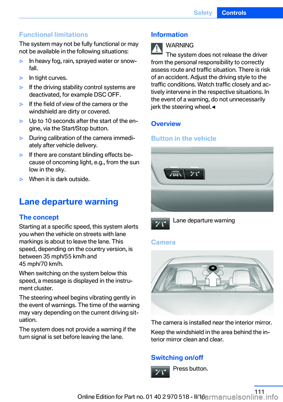
Button in the vehicle
Lane departure warning
Camera
The camera is installed near the interior mirror.
Keep the windshield in the area behind the in‐
terior mirror clean and clear.
Switching on/off Press button.
Seite 111SafetyControls111
Online Edition for Part no. 01 40 2 970 518 - II/16
Page 112 of 220
▷On: the LED lights up.▷Off: the LED goes out.
Settings are stored for the profile currently
used.
Display in the instrument cluster
▷Lines: system is activated.▷Arrows: at least one lane marking
was detected and warnings can be
issued.
Issued warning
If you leave the lane and if a lane marking has
been detected, the steering wheel begins vi‐
brating.
If the turn signal is set before changing the
lane, a warning is not issued.
End of warning
The warning is canceled in the following situa‐
tions:
▷Automatically after approx. 3 seconds.▷When returning to your own lane.▷When braking hard.▷When using the turn signal.
System limits
Information WARNING
The system can react incorrectly or not
at all due to the system limits. There is risk of
accidents or risk of property damage. Observe
the information regarding the system limits
and actively intervene, if needed.◀
Functional limitations
The system may not be fully functional in the
following situations:
▷In heavy fog, rain or snowfall.▷In the event of missing, worn, poorly visi‐
ble, merging, diverging, or multiple lane
markings such as in construction areas.▷When lane markings are covered in snow,
ice, dirt or water.▷In tight curves or on narrow lanes.▷When the lane markings are covered by
objects.▷When driving very close to the vehicle in
front of you.▷When driving toward bright lights.▷When the windshield in front of the interior
mirror is fogged over, dirty or covered with
stickers, etc.▷During calibration of the camera immedi‐
ately after vehicle delivery.
Brake force display
The concept
▷During normal brake application, the bot‐
tom brake lights light up.▷During heavy brake application, the top
brake lights light up in addition.
Attentiveness assistant
The concept The system can detect decreasing alertness or
fatigue of the driver during long, monotonous
trips, for example, on highways. In this situa‐
Seite 112ControlsSafety112
Online Edition for Part no. 01 40 2 970 518 - II/16
Page 123 of 220
3."Volume settings"4."PDC"5.Turn the Controller until the desired set‐
ting is selected.6.Press the Controller.
Settings are stored for the profile currently
used.
Visual warning
The approach of the vehicle to an object can
be shown on the Control Display. Objects that
are farther away are already displayed on the
Control Display before a signal sounds.
A display appears as soon as Park Distance
Control (PDC) is activated.
The range of the sensors is represented in the
colors green, yellow and red.
When the image of the rearview camera is dis‐
played, the switch can be made to PDC:
"Rear view camera"
System limits
Information WARNING
The system can react incorrectly or not
at all due to the system limits. There is risk of
accidents or risk of property damage. Observe
the information regarding the system limits
and actively intervene, if needed.◀
Limits of ultrasonic measurement Ultrasonic measuring might not function under
the following circumstances:
▷For small children and animals.▷For persons with certain clothing, for ex‐
ample coats.▷With external interference of the ultra‐
sound, for example from passing vehicles
or loud machines.▷When sensors are dirty, iced over, dam‐
aged or out of position.▷Under certain weather conditions such as
high relative humidity, rain, snowfall, ex‐
treme heat or strong wind.▷With tow bars and trailer couplings of other
vehicles.▷With thin or wedge-shaped objects.▷With moving objects.▷With elevated, protruding objects such as
ledges or cargo.▷With objects with corners and sharp edges.▷With objects with a fine surface structure
such as fences.▷For objects with porous surfaces.▷If cargo protrudes.
Low objects already displayed, for example,
curbs, can move into the blind area of the sen‐
sors before or after a continuous tone sounds.
False warnings
PDC may issue a warning under the following
conditions even though there is no obstacle
within the detection range:
▷In heavy rain.▷When sensors are very dirty or covered
with ice.▷When sensors are covered in snow.▷On rough road surfaces.▷On uneven surfaces, such as speed
bumps.▷In large buildings with right angles and
smooth walls, for example, in underground
garages.▷In automatic car washes.▷Through heavy pollution.▷Due to other ultrasound sources, for exam‐
ple, sweeping machines, high pressure
steam cleaners or neon lights.Seite 123Driving comfortControls123
Online Edition for Part no. 01 40 2 970 518 - II/16
Page 136 of 220

4.Likewise, press and hold the button of the
desired function on the hand-held trans‐
mitter.5.Release both buttons as soon as the inte‐
rior mirror LED flashes more rapidly. The
LED flashing faster indicates that the but‐
ton on the interior mirror has been pro‐
grammed. The system can then be con‐
trolled by the button on the interior mirror.
If the LED does not flash faster after at
least 60 seconds, change the distance and
repeat the step. Several more attempts at
different distances may be necessary. Wait
at least 15 seconds between attempts.
Canada: if programming with the hand-
held transmitter was interrupted, hold
down the interior mirror button and repeat‐
edly press and release the hand-held
transmitter button for 2 seconds.
Controls
WARNING
Body parts can be jammed when operat‐
ing remote-controlled systems, e.g., the ga‐
rage door, using the integrated universal re‐
mote control. There is a risk of injury or risk of
property damage. Make sure that the area of
movement of the respective system is clear
during programming and operation. Also follow
the safety instructions of the hand-held trans‐
mitter.◀
The system, such as the garage door, can be
operated using the button on the interior mirror
while the engine is running or when the ignition is started. To do this, hold down the button
within receiving range of the system until the
function is activated. The interior mirror LED
stays lit while the wireless signal is being
transmitted.
Deleting stored functions Press and hold the left and right button on the
interior mirror simultaneously for approxi‐
mately 20 seconds until the LED flashes rap‐
idly. All stored functions will be deleted. The
functions cannot be deleted individually.
Digital compass
Overview1Control button2Mirror display
Mirror display
The point of the compass is displayed in the
mirror when driving straight.
Operating concept
Various functions can be called up by pressing
the control button with a pointed object, such
as the tip of a ballpoint pen or similar object.
The following setting options are displayed in
succession, depending on how long the con‐
trol button is pressed:
▷Pressed briefly: turns display on/off.▷3 to 6 seconds: compass zone setting.▷6 to 9 seconds: compass calibration.▷9 to 12 seconds: left/right-hand steering
setting.▷12 to 15 seconds: language setting.
Setting the compass zones
Sets the particular compass zones on the vehi‐
cle so that the compass operates correctly; re‐
fer to World map with compass zones.
Seite 136ControlsInterior equipment136
Online Edition for Part no. 01 40 2 970 518 - II/16
Page 188 of 220

For checking and adjusting headlamp aim,
contact a dealer’s service center or another
qualified service center or repair shop.
Overview1Parking lights / daytime running lights2Low beams/high beams/headlight flasher3Turn signal
Xenon headlights
Low beams and high beams are designed with
xenon technology.
The parking lights and daylight running lights
are made using LED technology.
In the case of a malfunction, contact a dealer’s
service center or another qualified service cen‐
ter or repair shop.
Turn signal
Follow general instructions, refer to page 186.
21-watt bulb, PY21W1.In the wheel house, loosen the two brack‐
ets and remove the cover.2.If necessary, pull the inside trim of the
wheel house slightly inward. Turn the bulb
socket counterclockwise and remove.3.Press the bulb gently into the socket, turn
counterclockwise and remove.4.Install the new bulb and bulb holder in re‐
verse order of removal.5.Attach the cover to the wheel house.
Turn signal in exterior mirror
The turn signals in the exterior mirrors feature
LED technology. In the case of a malfunction,
contact a dealer’s service center or another
qualified service center or repair shop.
Seite 188MobilityReplacing components188
Online Edition for Part no. 01 40 2 970 518 - II/16
Page 189 of 220
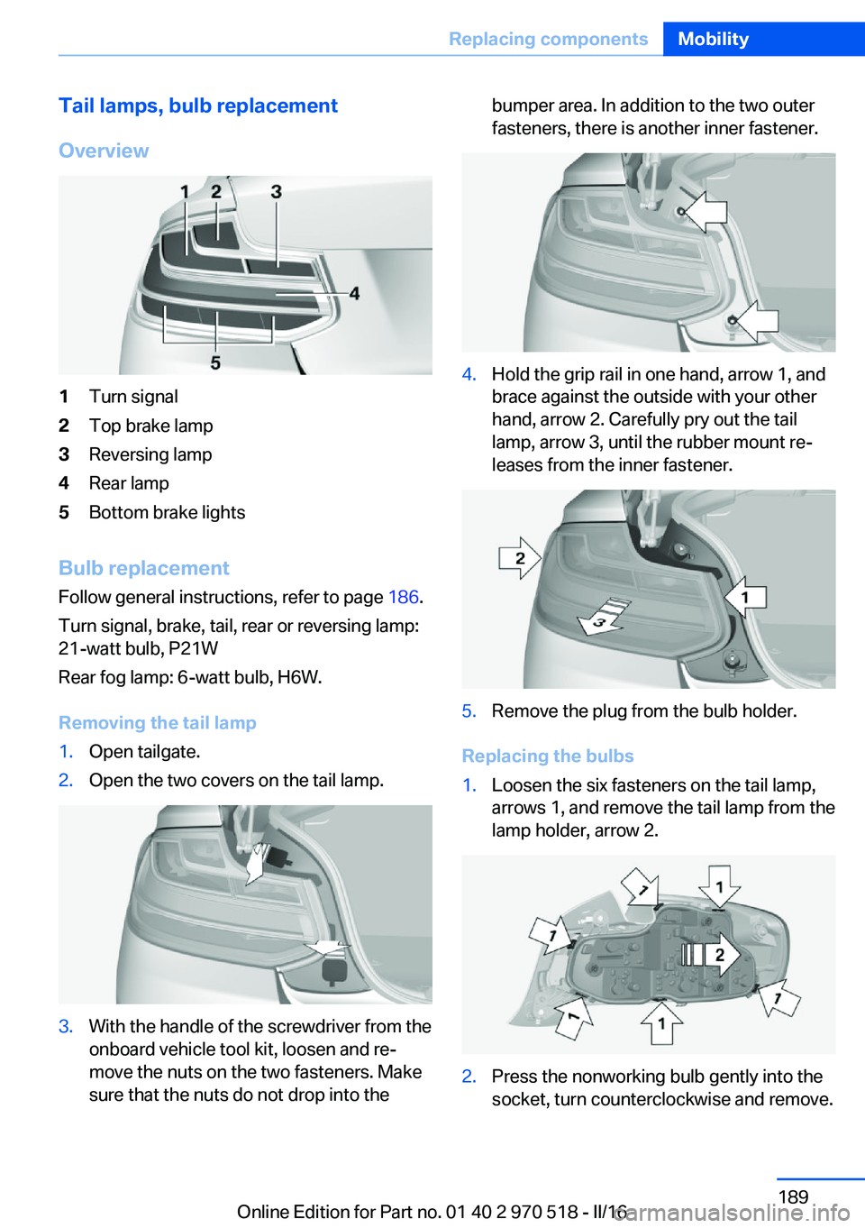
Tail lamps, bulb replacement
Overview1Turn signal2Top brake lamp3Reversing lamp4Rear lamp5Bottom brake lights
Bulb replacement Follow general instructions, refer to page 186.
Turn signal, brake, tail, rear or reversing lamp:
21-watt bulb, P21W
Rear fog lamp: 6-watt bulb, H6W.
Removing the tail lamp
1.Open tailgate.2.Open the two covers on the tail lamp.3.With the handle of the screwdriver from the
onboard vehicle tool kit, loosen and re‐
move the nuts on the two fasteners. Make
sure that the nuts do not drop into thebumper area. In addition to the two outer
fasteners, there is another inner fastener.4.Hold the grip rail in one hand, arrow 1, and
brace against the outside with your other
hand, arrow 2. Carefully pry out the tail
lamp, arrow 3, until the rubber mount re‐
leases from the inner fastener.5.Remove the plug from the bulb holder.
Replacing the bulbs
1.Loosen the six fasteners on the tail lamp,
arrows 1, and remove the tail lamp from the
lamp holder, arrow 2.2.Press the nonworking bulb gently into the
socket, turn counterclockwise and remove.Seite 189Replacing componentsMobility189
Online Edition for Part no. 01 40 2 970 518 - II/16