2016 BMW M2 inflation pressure
[x] Cancel search: inflation pressurePage 168 of 220

Wheels and tiresVehicle features and options
This chapter describes all standard, country-
specific and optional features offered with the
series. It also describes features that are not
necessarily available in your car, e. g., due to
the selected options or country versions. This
also applies to safety-related functions and
systems. The respectively applicable country
provisions must be observed when using the
respective features and systems.
Tire inflation pressure Safety information
The tire characteristics and tire inflation pres‐
sure influence the following:▷The service life of the tires.▷Road safety.▷Driving comfort.
Checking the tire inflation pressure
WARNING
A tire with low or missing tire inflation
pressure impacts handling, such as steering
and braking response. There is risk of an acci‐
dent. Regularly check the tire inflation pres‐
sure, and correct it as needed, e.g., twice a
month and before a long trip.◀
Tires have a natural, consistent loss of tire in‐
flation pressure.
Tires heat up while driving, and the tire infla‐
tion pressure increases along with the tire's
temperature. The tire inflation pressure speci‐
fications relate to cold tires or tires with the
ambient temperature.
Only check the tire inflation pressure when the
tires are cold. This means after driving no more
than 1.25 miles/2 km or when the vehicle has
been parked for at least 2 hours.
The displays of inflation devices may under-
read by up to 0.1 bar/2 psi.
For Flat Tire Monitor: after correcting the tire
inflation pressure, reinitialize the Flat Tire
Monitor.
For Tire Pressure Monitor: after correcting the
tire inflation pressure, reset the Tire Pressure
Monitor.
Tire inflation pressure specifications
The tire inflation pressure table, refer to
page 169, contains all tire inflation pressure
specifications for the specified tire sizes at the
ambient temperature. The tire inflation pres‐
sure values apply to tire sizes approved by the
manufacturer of the vehicle for the vehicle
type.
To identify the correct tire inflation pressure,
please note the following:▷Tire sizes of your vehicle.▷Maximum permitted driving speed.
Tire inflation pressures up to
100 mph/160 km/h
For speeds of up to 100 mph/160 km/h and for
optimum driving comfort, note the pressure
values in the tire inflation pressure table, refer
to page 169, and adjust as necessary.
Seite 168MobilityWheels and tires168
Online Edition for Part no. 01 40 2 970 518 - II/16
Page 169 of 220

These pressure values can also be found on
the tire inflation pressure label on the driver's
door pillar.
Do not exceed a speed of 100 mph/160 km/h.
Tire inflation pressure values up to
100 mph/160 km/h
M2
Tire sizePressure specifications in
bar/PSISpecifications in
bar/PSI with cold
tires235/40 R 18 95
V M+S XL Std2,1 / 302.3 / 33F: 245/35 R 19
93 (Y) XL Std2.4 / 35-R: 265/35 R 19
98 (Y) XL Std-2.4 / 35
Tire inflation pressures at max.
speeds above 100 mph/160 km/h
WARNING
In order to drive at maximum speeds in
excess of 100 mph/160 km/h, please observe,
and, if necessary, adjust tire pressures for
speeds exceeding 100 mph/160 km/h from the
relevant table on the following pages. Other‐
wise, tire damage and accidents could occur.◀
Tire inflation pressure values over
100 mph/160 km/h
M2Tire sizePressure specifications in
bar/PSISpecifications in
bar/PSI with cold
tires235/40 R 18 95
V M+S XL Std2.4 / 352.7 / 39F: 245/35 R 19
93 (Y) XL Std2.7 / 39-R: 265/35 R 19
98 (Y) XL Std-2.9 /42
Tire identification marks
Tire size 245/45 R 18 96 Y
245: nominal width in mm
45: aspect ratio in %
R: radial tire code
18: rim diameter in inches
96: load rating, not for ZR tires
Y: speed rating, before the R on ZR tires
Speed letter
Q = up to 100 mph, 160 km/h
R = up to 106 mph, 170 km/h
S = up to 112 mph, 180 km/h
T = up to 118 mph, 190 km/h
H = up to 131 mph, 210 km/h
V = up to 150 mph, 240 km/h
W = up to 167 mph, 270 km/h
Y = up to 186 mph, 300 km/h
Seite 169Wheels and tiresMobility169
Online Edition for Part no. 01 40 2 970 518 - II/16
Page 171 of 220

Tire treadSummer tires
Do not drive with a tire tread depth of less than
0.12 inches/3 mm.
There is an increased danger of hydroplaning if
the tire tread depth is less than 0.12 in‐
ches/3 mm.
Winter tires
Do not drive with a tire tread depth of less than
0.16 inches/4 mm.
Below a tread depth of 0.16 inches/4 mm, tires
are less suitable for winter operation.
Minimum tread depth
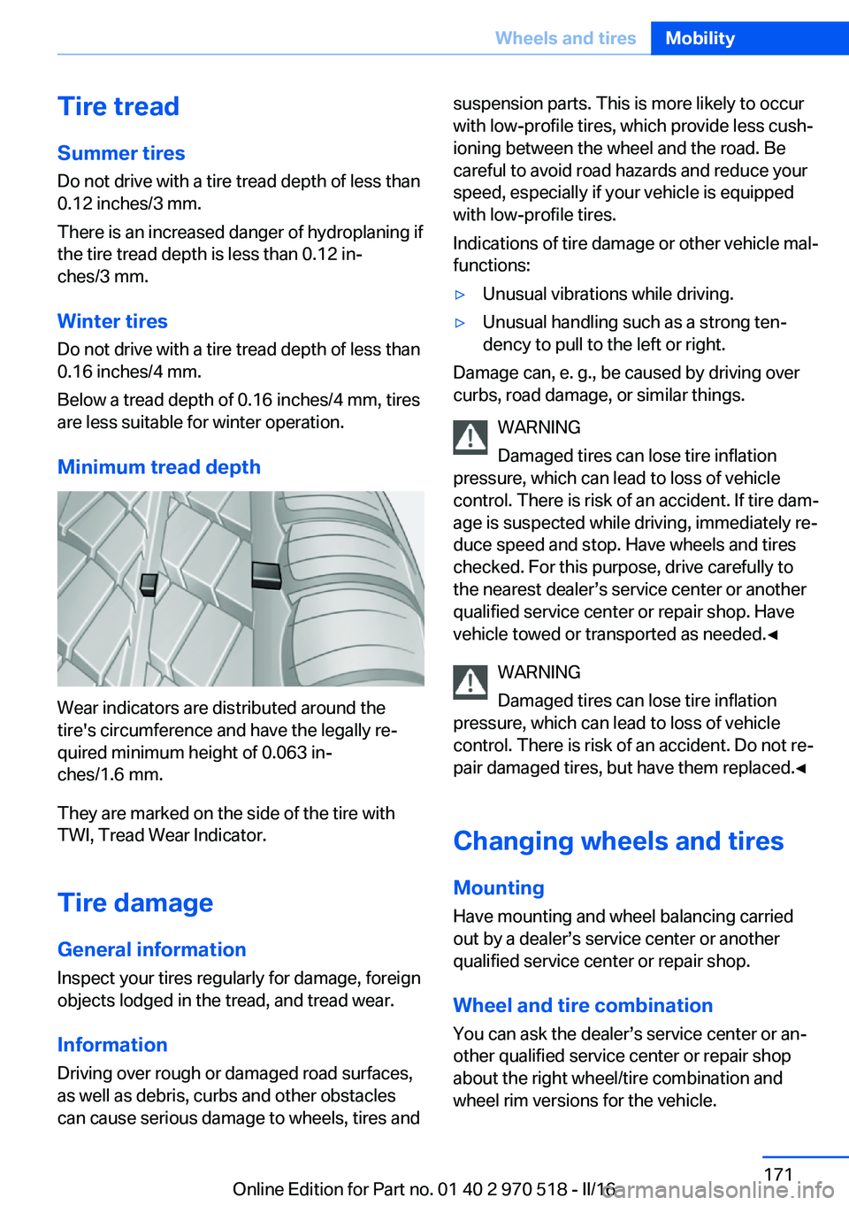
Wear indicators are distributed around the
tire's circumference and have the legally re‐
quired minimum height of 0.063 in‐
ches/1.6 mm.
They are marked on the side of the tire with
TWI, Tread Wear Indicator.
Tire damage
General information
Inspect your tires regularly for damage, foreign
objects lodged in the tread, and tread wear.
Information Driving over rough or damaged road surfaces,
as well as debris, curbs and other obstacles
can cause serious damage to wheels, tires and
suspension parts. This is more likely to occur
with low-profile tires, which provide less cush‐
ioning between the wheel and the road. Be
careful to avoid road hazards and reduce your
speed, especially if your vehicle is equipped
with low-profile tires.
Indications of tire damage or other vehicle mal‐
functions:▷Unusual vibrations while driving.▷Unusual handling such as a strong ten‐
dency to pull to the left or right.
Damage can, e. g., be caused by driving over
curbs, road damage, or similar things.
WARNING
Damaged tires can lose tire inflation
pressure, which can lead to loss of vehicle
control. There is risk of an accident. If tire dam‐
age is suspected while driving, immediately re‐
duce speed and stop. Have wheels and tires
checked. For this purpose, drive carefully to
the nearest dealer’s service center or another
qualified service center or repair shop. Have
vehicle towed or transported as needed.◀
WARNING
Damaged tires can lose tire inflation
pressure, which can lead to loss of vehicle
control. There is risk of an accident. Do not re‐
pair damaged tires, but have them replaced.◀
Changing wheels and tires
Mounting Have mounting and wheel balancing carriedout by a dealer’s service center or another
qualified service center or repair shop.
Wheel and tire combination
You can ask the dealer’s service center or an‐
other qualified service center or repair shop
about the right wheel/tire combination and
wheel rim versions for the vehicle.
Seite 171Wheels and tiresMobility171
Online Edition for Part no. 01 40 2 970 518 - II/16
Page 173 of 220

Do not exceed the maximum tire inflation pres‐
sure indicated on the side wall of the tire.
Repairing a flat tire
Safety measures▷Park the vehicle as far away as possible
from passing traffic and on solid ground.▷Switch on the hazard warning system.▷Secure the vehicle against rolling away by
setting the parking brake.▷Turn the steering wheel until the front
wheels are in the straight-ahead position
and engage the steering wheel lock.▷Have all vehicle occupants get out of the
vehicle and ensure that they remain out‐
side the immediate area in a safe place,
such as behind a guardrail.▷If necessary, set up a warning triangle at an
appropriate distance.
Mobility System
The concept
With the Mobility System, minor tire damage
can be sealed temporarily to enable continued
travel. To accomplish this, sealant is pumped
into the tires, which seals the damage from the
inside.
The compressor can be used to check the tire
inflation pressure.
Information
▷Follow the instructions on using the Mobi‐
lity System found on the compressor and
sealant container.▷Use of the Mobility System may be ineffec‐
tive if the tire puncture measures approx.
1/8 in/4 mm or more.▷Contact a dealer’s service center or an‐
other qualified service center or repair
shop if the tire cannot be made drivable.▷If possible, do not remove foreign bodies
that have penetrated the tire.▷Pull the speed limit sticker off the sealant
container and apply it to the steering
wheel.▷The use of a sealant can damage the TPM
wheel electronics. In this case, have the
electronics checked at the next opportu‐
nity and have them replaced if needed.
DANGER
If the exhaust pipe is blocked or ventila‐
tion is insufficient, harmful exhaust gases can
enter into the vehicle. The exhaust gases con‐
tain carbon monoxide, an odorless and color‐
less but highly toxic gas. In enclosed areas, ex‐
haust gases can also accumulate outside of
the vehicle. There is danger to life. Keep the
exhaust pipe free and ensure sufficient ventila‐
tion.◀
Storage
The Mobility System is located under the cargo floor panel.
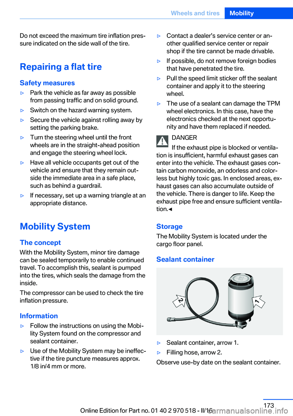
Sealant container
▷Sealant container, arrow 1.▷Filling hose, arrow 2.
Observe use-by date on the sealant container.
Seite 173Wheels and tiresMobility173
Online Edition for Part no. 01 40 2 970 518 - II/16
Page 174 of 220

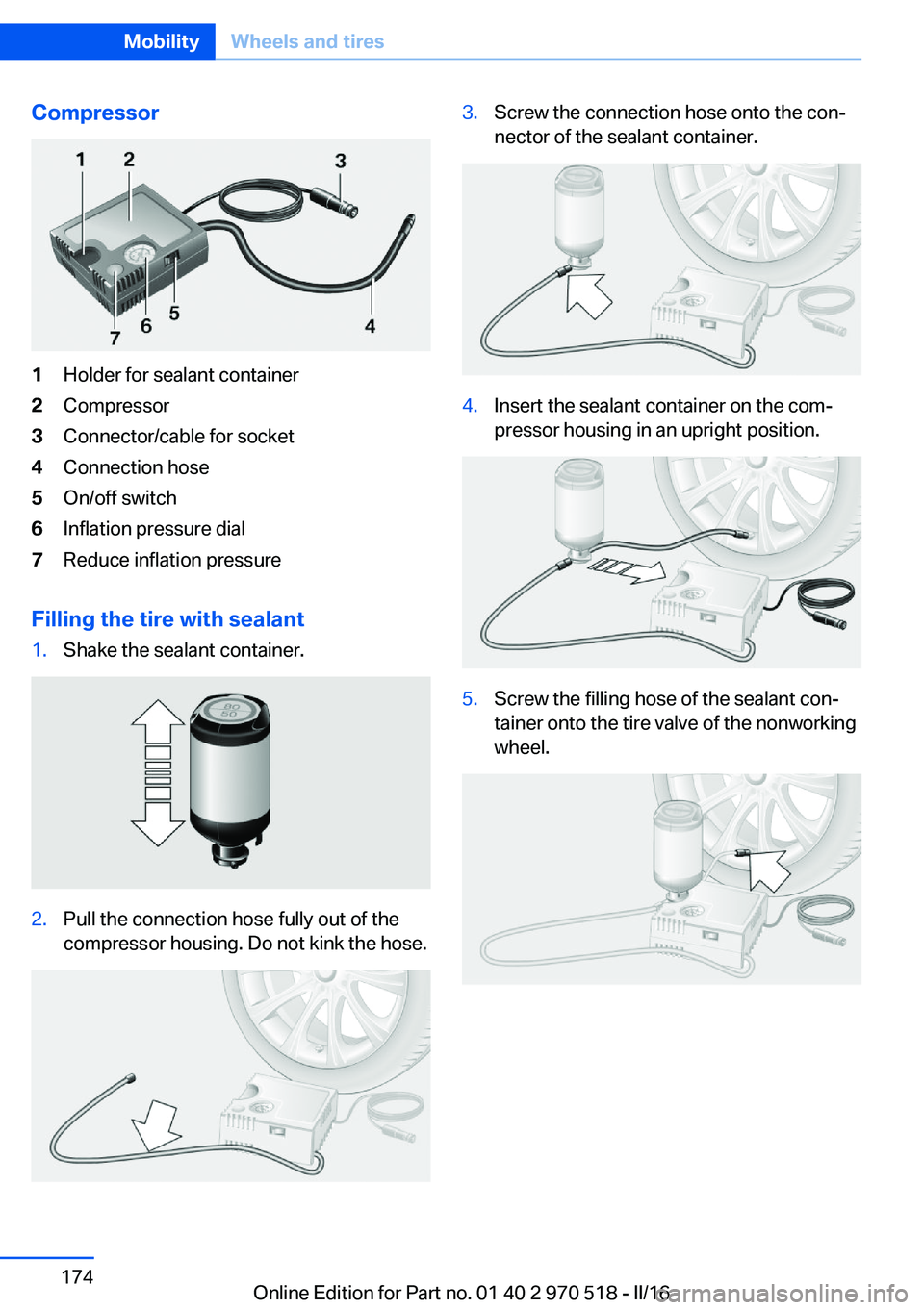
Compressor1Holder for sealant container2Compressor3Connector/cable for socket4Connection hose5On/off switch6Inflation pressure dial7Reduce inflation pressure
Filling the tire with sealant
1.Shake the sealant container.2.Pull the connection hose fully out of the
compressor housing. Do not kink the hose.3.Screw the connection hose onto the con‐
nector of the sealant container.4.Insert the sealant container on the com‐
pressor housing in an upright position.5.Screw the filling hose of the sealant con‐
tainer onto the tire valve of the nonworking
wheel.Seite 174MobilityWheels and tires174
Online Edition for Part no. 01 40 2 970 518 - II/16
Page 175 of 220

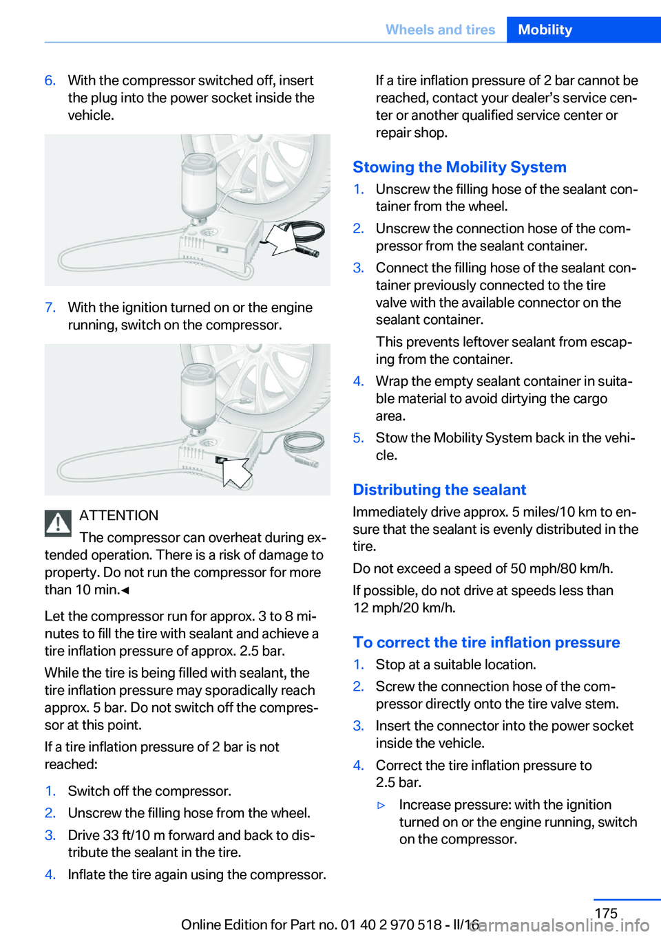
6.With the compressor switched off, insert
the plug into the power socket inside the
vehicle.7.With the ignition turned on or the engine
running, switch on the compressor.
ATTENTION
The compressor can overheat during ex‐
tended operation. There is a risk of damage to
property. Do not run the compressor for more
than 10 min.◀
Let the compressor run for approx. 3 to 8 mi‐
nutes to fill the tire with sealant and achieve a
tire inflation pressure of approx. 2.5 bar.
While the tire is being filled with sealant, the
tire inflation pressure may sporadically reach
approx. 5 bar. Do not switch off the compres‐
sor at this point.
If a tire inflation pressure of 2 bar is not
reached:
1.Switch off the compressor.2.Unscrew the filling hose from the wheel.3.Drive 33 ft/10 m forward and back to dis‐
tribute the sealant in the tire.4.Inflate the tire again using the compressor.If a tire inflation pressure of 2 bar cannot be
reached, contact your dealer’s service cen‐
ter or another qualified service center or
repair shop.
Stowing the Mobility System
1.Unscrew the filling hose of the sealant con‐
tainer from the wheel.2.Unscrew the connection hose of the com‐
pressor from the sealant container.3.Connect the filling hose of the sealant con‐
tainer previously connected to the tire
valve with the available connector on the
sealant container.
This prevents leftover sealant from escap‐
ing from the container.4.Wrap the empty sealant container in suita‐
ble material to avoid dirtying the cargo
area.5.Stow the Mobility System back in the vehi‐
cle.
Distributing the sealant
Immediately drive approx. 5 miles/10 km to en‐
sure that the sealant is evenly distributed in the
tire.
Do not exceed a speed of 50 mph/80 km/h.
If possible, do not drive at speeds less than
12 mph/20 km/h.
To correct the tire inflation pressure
1.Stop at a suitable location.2.Screw the connection hose of the com‐
pressor directly onto the tire valve stem.3.Insert the connector into the power socket
inside the vehicle.4.Correct the tire inflation pressure to
2.5 bar.▷Increase pressure: with the ignition
turned on or the engine running, switch
on the compressor.Seite 175Wheels and tiresMobility175
Online Edition for Part no. 01 40 2 970 518 - II/16
Page 190 of 220

3.Proceed in the reverse order to insert the
new bulb and attach the bulb holder to the
tail lamp. Make sure that the bulb holder
engages in all fasteners.
Installing the tail lamp
1.Connect the plug to the bulb holder.2.Insert the tail lamp straight in and press it
in, arrow 1, until the rubber mount latches
in the inner fastener. Make sure when in‐
serting the tail lamp that the rubber lip, ar‐
row 2, on the top side of the tail lamp does
not fold over. Screw on the two nuts, ar‐
row 3, and close covers.
Central brake lamp and license plate
lamp
Follow general instructions, refer to page 186.
These lights are made using LED technology.
In the case of a malfunction, contact a dealer’s
service center or another qualified service cen‐
ter or repair shop.
Changing wheels/tires General information
When sealants are used, an immediate wheel
change when there is a loss of tire inflation
pressure in the event of a flat tire is unneces‐
sary.
No spare tire is provided with your vehicle.
If needed, the tools for changing wheels are
available as accessories from a dealer’s service
center or another qualified service center or re‐
pair shop.
Jacking points for the vehicle jack
The jacking points for the vehicle jack are lo‐
cated at the positions shown.
Vehicle battery Maintenance
The battery is maintenance-free.
The added amount of acid is sufficient for the
service life of the battery.
More information about the battery can be re‐
quested from a dealer’s service center or an‐
other qualified service center or repair shop.
Battery replacement ATTENTION
Vehicle batteries that are not compatible
can damage vehicle systems and impair vehi‐
cle functions. There is a risk of personal and
property damage. Only vehicle batteries that
are compatible with your vehicle type should
be installed in your vehicle. Information on
compatible vehicle batteries is available at your
dealer’s service center.◀
After a battery replacement, the manufacturer
of your vehicle recommends that the vehicle
battery be registered on the vehicle by a
dealer’s service center or another qualified
service center or repair shop to ensure that all
comfort features are fully available and that any
Seite 190MobilityReplacing components190
Online Edition for Part no. 01 40 2 970 518 - II/16
Page 213 of 220

Flat Tire Monitor FTM 104
Flat tire, repairing 173
Flat tire, Tire Pressure Moni‐ tor TPM 101
Flat tire, warning lamp 102, 105
Flooding 153
Floor carpet, care 202
Floor mats, care 202
Fogged up windows 129
Fold-away position, wiper 73
Fold down the rear seat back‐ rest, see Though-loading
system 141
Foot brake 153
Front airbags 98
Front-end collision warning with City Braking func‐
tion 106
Front lights 187
Front-seat passenger airbags, automatic deactivation 100
Front-seat passenger airbags, indicator lamp 101
FTM Flat Tire Monitor 104
Fuel 166
Fuel cap 164
Fuel consumption, see Aver‐ age fuel consumption 89
Fuel filler flap 164
Fuel gauge 83
Fuel quality 166
Fuel recommendation 166
Fuel, tank capacity 207
Fuse 191
G
Garage door opener, see Uni‐ versal Integrated Remote
Control 134
Gasoline 166
Gear change 77
Gear shift indicator 86
General driving notes 153
Glare shield 138 Glass sunroof, powered 47
Glove compartment 143
GPS location, vehicle posi‐ tion 92
Gross vehicle weight, ap‐ proved 207
Ground clearance 155
H
Handbrake, see parking brake 70
Hand-held transmitter, alter‐ nating code 135
Hazard warning flashers 193
Head airbags 98
Headlamp control, auto‐ matic 94
Headlight courtesy delay fea‐ ture 94
Headlight flasher 71
Headlight glass 187
Headlights 187
Headlights, care 200
Head restraints 49
Head restraints, front 54
Head restraints, rear 55
Heavy cargo, stowing 157
High-beam Assistant 95
High beams 71
High beams/low beams, see High-beam Assistant 95
High-performance en‐ gine 150
Hills 154
Hill start assistant, see Drive- off assistant 118
Holder for beverages 145
Homepage 6
Hood 177
Horn 14
Hotel function, tailgate 41
Hot exhaust system 153
Hydroplaning 153 I
Ice warning, see External temperature warning 84
Icy roads, see External tem‐ perature warning 84
Identification marks, tires 169
Identification number, see Ve‐ hicle identification num‐
ber 10
iDrive 18
Ignition key, see Remote con‐ trol 34
Ignition off 65
Ignition on 65
Indication of a flat tire 102 , 105
Indicator and alarm lamps, see Check Control 80
Indicator lamp, see Check Control 80
Individual air distribu‐ tion 129, 131
Individual settings, see Per‐ sonal Profile 36
Inflation pressure, tires 168
Inflation pressure warning, tires 104
Info display, see On-Board computer 88
Information 6
Initialize, Tire Pressure Moni‐ tor TPM 102
Initializing, Flat Tire Monitor FTM 104
Instrument cluster 79
Instrument cluster, electronic displays 79
Instrument lighting 96
Integrated key 34
Integrated Owner's Manual in the vehicle 30
Intelligent emergency call 193
Intelligent Safety 105 Seite 213Everything from A to ZReference213
Online Edition for Part no. 01 40 2 970 518 - II/16