2016 BMW M2 automatic transmission
[x] Cancel search: automatic transmissionPage 75 of 220

M double-clutch
transmission with Drivelogic
General information
The M double-clutch transmission with Drive‐
logic is an automatic shift transmission with
two clutches and partial transmissions in which
the gears can be changed without interrupting
the tractive force.
The operation is via the selector lever or two
shift paddles on the steering wheel.
Functions▷Drive mode or Sequential mode.▷Various drive programs, Drivelogic.▷Automatic downshifting and protection
from misshifting even in sequential mode.▷Launch Control.▷Low Speed Assistant.
Information
WARNING
An unsecured vehicle can begin to move
and possibly roll away. There is risk of an acci‐
dent. Before exiting, secure the vehicle against
rolling.
In order to ensure that the vehicle is secured
against rolling away, observe the following:
▷Set the parking brake.▷On uphill grades or on a downhill slope,
turn the front wheels in the direction of the
curb.▷On uphill grades or on a downhill slope,
also secure the vehicle, e.g., with a wheel
chock.◀Selector lever, selector lever positions
Overview▷R: reverse gear.▷N: neutral.▷ Center position, forward position.▷+: manual upshifting.▷-: manual downshifting.▷D/S: switch between drive mode and se‐
quential mode.
Engaging a selector lever position
Press on the brake pedal and pull or push the
selector lever in the corresponding direction.
As soon as the selector lever is released, it re‐
verts to the center position. In position R, the
selector lever locks.
The engaged selector lever position is dis‐
played in the instrument cluster and on the se‐
lector lever.
If a selector lever position is engaged, the vehi‐
cle may start rolling, after the brake is released,
for example on downhill slopes. Thus, drive off
immediately after releasing the brake.
Use the Slow Speed Assistant for maneuver‐
ing and during stop-and-go traffic.
Low Speed Assistant
The concept
The Low Speed Assistant gives assistance at
very low speeds. The vehicle moves at walking
speed.
Seite 75DrivingControls75
Online Edition for Part no. 01 40 2 970 518 - II/16
Page 76 of 220

This can also be used for rocking the vehicle in
the snow. To do this, switch between reverse
gear and forward gear without stepping on the
brakes in the process.
Information CAUTION
When using the function and simultane‐
ously stepping on the brake pedal for a longer
time, the transmission can overheat. There is a
risk of property damage. When using the func‐
tion, do not brake for a longer period.◀
Activating1.Engage a driving position.2.Briefly tap the accelerator pedal.
The vehicle rolls at minimum speed.
This is possible in 1st and 2nd gear and in re‐
verse gear.
Deactivating
Apply the brakes until the vehicle comes to a
stop.
Flashing display on the selector lever of the double clutch transmission
The actually engaged transmission position
can deviate from the selector lever position in
some situations. The display in the selector
lever flashes.
Observe the display in the instrument cluster
in these cases.
D is Drive mode In Drive mode, all forward gears are automati‐
cally changed.
Kickdown: for maximum acceleration, e.g.
when passing. To do this, depress the acceler‐
ator pedal past the resistance point.
Switch to Sequential mode: shift using the
shift paddles or the selector lever, or push the
selector lever in the D/S direction.
S is Sequential mode
Use the shift paddles or the selector lever to
upshift or downshift without letting off the gas.▷Shortly before falling below a gear-de‐
pendent minimum speed, the transmission
is automatically downshifted.▷Upshifting or downshifting is done only if
the rpm and vehicle speed are appropriate.
For example, there is no downshifting if the
engine speed is too high.▷Kickdown: the lowest possible gear is se‐
lected by simultaneously operating the
kickdown and the left shift paddle or selec‐
tor lever.▷It is also possible to start out in 2nd gear,
for example, on icy roads.
Switch to Drive mode: push selector lever in
D/S direction.
R is Reverse
Select only when the vehicle is stationary.
It is also possible to rock the vehicle up to
6 mph/10 km/h. To do this, switch between
forward gear and reverse gear without step‐
ping on the brakes in the process.
N Neutral
The vehicle may roll in selector lever posi‐
tion N, for example, in car washes, refer to
page 199.
P is Park
The drive wheels are blocked.
P is engaged automatically:
▷After the engine is switched off, if the car is
in radio-ready state, refer to page 65, or if
the ignition is switched off, refer to
page 65, and if position R or D is set.▷With the ignition is off, if position N is set.Seite 76ControlsDriving76
Online Edition for Part no. 01 40 2 970 518 - II/16
Page 78 of 220

Launch Control
The concept Launch Control enables optimum accelerationon surfaces with good traction.
General information
The use of Launch Control causes premature
component wear since this function represents
a very heavy load for the vehicle.
Do not use Launch Control during the break-in,
refer to page 152, period.
Requirements Launch Control is available when the engine is
warmed up, that is, after uninterrupted driving
of at least 6 miles/10 km.
To start with Launch Control do not steer the
steering wheel.
Activate Launch Control1.Deactivate Dynamic Stability Control, refer
to page 114.2.Select Sequential mode with gear 1.3.With the engine running, apply the brake
with the left foot.4.Fully depress the accelerator pedal.
The starting engine speed adjusts.5.If necessary, change the starting engine
speed by 500 rpm via cruise control.6.Release the brake, the vehicle accelerates.
Continue to depress the accelerator pedal.
Upshifting occurs automatically as long as
the accelerator pedal is fully depressed.
Launch Control is available again only after a
certain distance has been driven.
System limits
This transmission has an overheating protec‐
tion mechanism, which protects the clutch
from extreme stress.
▷Indicator lamp lights up yellow:
transmission too hot.
Avoid high engine stress and fre‐
quent starts.▷Indicator lamp lights up red: transmission
is overheating.
Further driving at a moderate pace is pos‐
sible. At the next opportunity, stop the car,
shut off the engine and allow the transmis‐
sion to cool down.
Avoid fast starts, and on inclines did not accel‐
erate lightly while letting the clutch slip; other‐
wise, the transmission may overheat.
During traffic jams or at very low speeds, use
the Low Speed Assistant, refer to page 75.
Seite 78ControlsDriving78
Online Edition for Part no. 01 40 2 970 518 - II/16
Page 86 of 220

6.Adjust the settings.7.Confirm.
The entered date is stored.
Automatic Service Request
Data regarding the service status or legally
mandated vehicle inspections are automati‐
cally transmitted to your dealer’s service cen‐
ter before a service due date.
You can check when your dealer’s service cen‐
ter was notified.
On the Control Display:
1."Vehicle info"2."Vehicle status"3.Open "Options".4."Last Service Request"
Gear shift indicator
The conceptThe system recommends the most fuel effi‐
cient gear for the current driving situation.
General information
The gear shift indicator is active in the sequen‐
tial mode of the M double clutch transmission
and for the manual transmission.
Suggestions to shift gear up or down are dis‐
played in the instrument cluster.
On vehicles without a gear shift indicator, the
engaged gear is displayed.
Manual transmission: displaying
SymbolDescriptionFuel efficient gear is set.Shift up to fuel efficient gear.SymbolDescriptionShift down to fuel efficient gear.Shift into neutral.
M double-clutch transmission:
displaying
ExampleDescriptionFuel efficient gear is set.Shift into fuel efficient gear.
Speed limit detection
The concept
Speed limit detection
Speed limit detection shows the current maxi‐
mum permitted speed in the instrument clus‐
ter. The camera in the area of the interior mir‐
ror detects traffic signs at the edge of the road
as well as variable overhead sign posts. Traffic
signs with extra symbols for wet road condi‐
tions, etc. are also detected and compared
with the vehicle's onboard data, such as for the
rain sensor, and will be displayed depending
on the situation. The system takes into ac‐
count the information stored in the navigation
system and also displays speed limits present
on routes without signs.
Information WARNING
The system does not release from the
personal responsibility to correctly assess visi‐
bility and traffic situation. There is risk of an ac‐
Seite 86ControlsDisplays86
Online Edition for Part no. 01 40 2 970 518 - II/16
Page 108 of 220

The driver must intervene actively when there
is an acute warning. If necessary, the driver is
assisted by a minor automatic braking inter‐
vention in a possible risk of collision.
Acute warnings can also be triggered without
previous forewarning.
Braking intervention
The warning prompts the driver himself/herself
to react. During a warning, the maximum brak‐
ing force is used. Premise for the brake boos‐
ter is sufficiently quick and hard stepping on
the brake pedal. The system can assist with some braking intervention if there is a risk of a
collision. At low speeds vehicles may thus
come to a complete stop.
Manual transmission: During a braking inter‐
vention up to a complete stop, the engine may
be shut down.
The braking intervention is executed only if ve‐
hicle stability has not been restricted, e.g. by
deactivating the DSC Dynamic Stability Con‐
trol.
The braking intervention can be interrupted by
stepping on the accelerator pedal or by ac‐
tively moving the steering wheel.
Object detection can be restricted. Limitations
of the detection range and functional restric‐
tions are to be considered.
System limits
Information WARNING
The system can react incorrectly or not
at all due to the system limits. There is risk of
accidents or risk of property damage. Observe
the information regarding the system limits
and actively intervene, if needed.◀
Detection range
The system's detection potential is limited.Thus a system reaction might not come or
might come late.
E. g. the following situations may not be de‐
tected:▷Slow moving vehicles when you approach
them at high speed.▷Vehicles that suddenly swerve in front of
you, or sharply decelerating vehicles.▷Vehicles with an unusual rear appearance.▷Two-wheeled vehicles ahead of you.
Functional limitations
The system may not be fully functional in the
following situations:
▷In heavy fog, rain, sprayed water or snow‐
fall.▷In tight curves.▷If the driving stability control systems are
limited or deactivated, for example, DSC
OFF.▷If the field of view of the camera in the mir‐
ror is dirty or obscured.▷Up to 10 seconds after the start of the en‐
gine, via the Start/Stop button.▷During calibration of the camera immedi‐
ately after vehicle delivery.▷If there are constant blinding effects be‐
cause of oncoming light, e. g., from the sun
low in the sky.
Warning sensitivity
The more sensitive the warning settings are,
for example the warning time, the more warn‐
ings are displayed. However, there may also be
an excess of false warnings.
Seite 108ControlsSafety108
Online Edition for Part no. 01 40 2 970 518 - II/16
Page 110 of 220

Camera
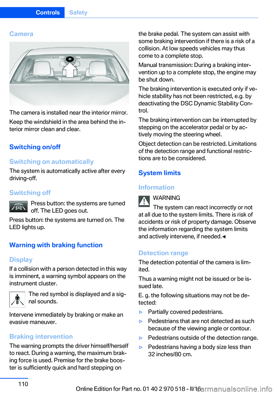
The camera is installed near the interior mirror.
Keep the windshield in the area behind the in‐
terior mirror clean and clear.
Switching on/off
Switching on automatically The system is automatically active after every
driving-off.
Switching off Press button: the systems are turned
off. The LED goes out.
Press button: the systems are turned on. The
LED lights up.
Warning with braking function
Display
If a collision with a person detected in this way
is imminent, a warning symbol appears on the
instrument cluster.
The red symbol is displayed and a sig‐
nal sounds.
Intervene immediately by braking or make an
evasive maneuver.
Braking intervention The warning prompts the driver himself/herself
to react. During a warning, the maximum brak‐
ing force is used. Premise for the brake boos‐
ter is sufficiently quick and hard stepping on
the brake pedal. The system can assist with
some braking intervention if there is a risk of a
collision. At low speeds vehicles may thus
come to a complete stop.
Manual transmission: During a braking inter‐
vention up to a complete stop, the engine may
be shut down.
The braking intervention is executed only if ve‐
hicle stability has not been restricted, e.g. by
deactivating the DSC Dynamic Stability Con‐
trol.
The braking intervention can be interrupted by
stepping on the accelerator pedal or by ac‐
tively moving the steering wheel.
Object detection can be restricted. Limitations
of the detection range and functional restric‐
tions are to be considered.
System limits
Information WARNING
The system can react incorrectly or not
at all due to the system limits. There is risk of
accidents or risk of property damage. Observe
the information regarding the system limits
and actively intervene, if needed.◀
Detection range The detection potential of the camera is lim‐
ited.
Thus a warning might not be issued or be is‐
sued late.
E. g. the following situations may not be de‐
tected:▷Partially covered pedestrians.▷Pedestrians that are not detected as such
because of the viewing angle or contour.▷Pedestrians outside of the detection range.▷Pedestrians having a body size less than
32 inches/80 cm.Seite 110ControlsSafety110
Online Edition for Part no. 01 40 2 970 518 - II/16
Page 140 of 220

USB interface in the glove
compartment
Mobile storage devices with USB port can be
connected to the USB interface in the glove
compartment.
Common file systems are supported. FAT32
and exFAT are the recommended formats.
The following applications are possible:▷Exporting and importing profiles, refer to
page 36.▷Loading of software updates.▷Adding music files to the music collection
and saving the music collection.
USB interface in the center console
In addition to the USB storage devices descri‐
bed above, additional mobile devices with USB
port can be connected to the USB interface in
the center console.
▷Mobile phones supported by the USB in‐
terface.
The snap-in adapter features a separate
USB port that is automatically connected
when a compatible mobile phone is in‐
serted.▷Audio devices with USB port, for example
MP3 player.
This allows further uses:
▷Playing music files via USB audio.▷Playing video films via USB video.
Information about compatible USB devices can
be found at www.bmwusa.com/bluetooth.
Information Observe the following when connecting:
▷Do not use force when plugging the con‐
nector into the USB interface.▷Use a flexible adapter cable.▷Protect the USB device against mechanical
damage.▷Due to the large number of USB devices
available on the market, it cannot be guar‐
anteed that every device is operable on the
vehicle.▷Do not expose USB devices to extreme en‐
vironmental conditions, such as very high
temperatures; refer to the owner's manual
of the device.▷Due to the many different compression
techniques, proper playback of the media
stored on the USB device cannot be guar‐
anteed in all cases.▷A connected USB device is supplied with
charging current via the USB interface, as‐
suming this is supported by the device.▷To ensure proper transmission of the
stored data, do not charge an USB device
via the onboard socket, when it is con‐
nected to the USB interface.▷Depending on how the USB device should
be used, settings may be required on the
USB device, refer to the owner's manual of
the device.
Not suitable USB devices:
▷USB hard drives.▷USB hubs.▷USB memory card readers with multiple in‐
serts.▷HFS-formatted USB devices.▷MTP devices.▷Devices such as fans or lights.Seite 140ControlsInterior equipment140
Online Edition for Part no. 01 40 2 970 518 - II/16
Page 154 of 220

In certain braking situations, the perforated
brake discs can emit functional noises. How‐
ever, this has no effect on the performance and
operational reliability of the brake.
Objects in the movement area around
pedals and floor area
WARNING
Objects in the driver's floor area can limit
the pedal distance or block a depressed pedal.
There is risk of an accident. Stow objects in
the vehicle such that they are secured and
cannot enter into the driver's floor area. Use
floor mats that are suitable for the vehicle and
can be safely attached to the floor. Do not use
loose floor mats and do not layer several floor
mats. Make sure that there is sufficient clear‐
ance for the pedals. Ensure that the floor mats
are securely fastened again after they were re‐
moved, e.g., for cleaning.◀
Driving in wet conditionsWhen roads are wet, salted, or in heavy rain,
press brake pedal ever so gently every few
miles.
Ensure that this action does not endanger
other traffic.
The heat generated in this process helps dry
the brake discs and pads.
In this way braking efficiency will be available
when you need it.
Hills WARNING
Light but consistent brake pressure can
lead to high temperatures, brakes wearing out
and possibly even brake failure. There is risk of
an accident. Avoid placing excessive stress on
the brake system.◀
WARNING
In idle state or with the engine switched
off, safety-relevant functions are restricted or
not available anymore, e.g., braking effect ofthe engine or braking force and steering sup‐
port. There is risk of an accident. Do not drive
in idle state or with the engine switched off.◀
Drive long or steep downhill gradients in the
gear that requires least braking efforts. Other‐
wise the brakes may overheat and reduce
brake efficiency.
Manual transmission:
You can increase the engine's braking effect
by shifting down, going all the way to first gear,
if needed.
M double-clutch transmission:
You can increase the engine's braking effect
by shifting down in sequential mode, refer to
page 76.
Brake disc corrosion
Corrosion on the brake discs and contamina‐
tion on the brake pads are furthered by the fol‐
lowing circumstances:▷Low mileage.▷Extended periods when the vehicle is not
used at all.▷Infrequent use of the brakes.
Corrosion will built up when the maximum
pressure applied to the brake pads during
braking is not reached - thus discs don't get
cleaned.
Corrosion buildup on the brake discs will cause
a pulsating effect on the brakes in their re‐
sponse - generally that cannot be corrected.
Condensation under the parked
vehicle
When using the automatic climate control,
condensation water develops collecting under‐
neath the vehicle.
Seite 154Driving tipsThings to remember when driving154
Online Edition for Part no. 01 40 2 970 518 - II/16