2016 BMW M2 COUPE tailgate
[x] Cancel search: tailgatePage 57 of 220

Overview
Storing
1.Switch on the ignition.2.Set the desired position.3. Press button. The LED in the but‐
ton lights up.4.Press selected button 1 or 2 while the LED
is lit. The LED goes out.
Button was pressed inadvertently:
Press button again.
The LED goes out.
Calling up settings
General information
There are two ways to call up the memory
function:
▷Comfort function.▷Safety function.
Comfort function
1.Open the driver's door.2.If necessary, switch off the ignition.3.Briefly press the desired button 1 or 2.
The corresponding seat position is performed
automatically.
The procedure stops when a switch for adjust‐
ing the seat or one of the buttons is pressed.
Safety mode1.Close the driver's door or switch on the ig‐
nition.2.Press and hold the desired button 1 or 2
until the adjustment procedure is com‐
pleted.
Calling up of a seat position
deactivated
After a brief period, calling up stored seat posi‐
tions is deactivated to save battery power.
To reactivate calling up of a seat position:
▷Open and close the door or tailgate.▷Press a button on the remote control.▷Press the Start/Stop button.
Mirrors
Exterior mirrors
General information The mirror on the passenger side is more
curved than the driver's side mirror.
Depending on the vehicle equipment, the mir‐
ror setting is stored for the profile currently
used. When the vehicle is unlocked via the re‐
mote control, the position is automatically re‐
trieved if this function is active.
Information WARNING
Objects reflected in the mirror are closer
than they appear. The distance to the traffic
behind could be incorrectly estimated, e.g.,
while changing lanes. There is risk of an acci‐
dent. Estimate the distance to the traffic be‐
hind by looking over your shoulder.◀
Seite 57AdjustingControls57
Online Edition for Part no. 01 40 2 970 518 - II/16
Page 124 of 220
As soon as the malfunction due to other ultra‐
sound sources is no longer present, the sys‐
tem is again fully functional.
Malfunction
A Check Control message is displayed.
The range of the sensors is shown as a shaded
area on the Control Display.
PDC has failed. Have the system checked.
Rearview camera The concept
The rearview camera provides assistance in
parking and maneuvering backwards. The area
behind the vehicle is shown on the Control
Display.
Information WARNING
The system does not relieve from the
personal responsibility to correctly assess the
traffic situation. There is risk of an accident.
Adjust the driving style to the traffic condi‐
tions. Watch traffic and vehicle surroundings
closely and actively intervene in the respective
situations.◀Overview
Camera
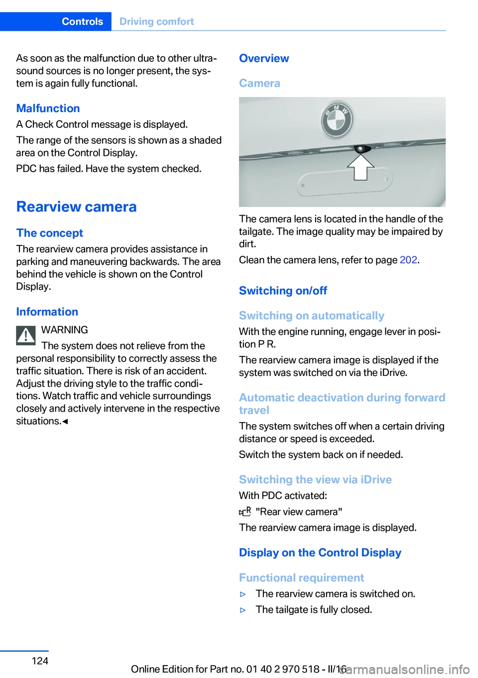
The camera lens is located in the handle of the
tailgate. The image quality may be impaired by
dirt.
Clean the camera lens, refer to page 202.
Switching on/off
Switching on automatically With the engine running, engage lever in posi‐
tion P R.
The rearview camera image is displayed if the
system was switched on via the iDrive.
Automatic deactivation during forward
travel
The system switches off when a certain driving
distance or speed is exceeded.
Switch the system back on if needed.
Switching the view via iDrive With PDC activated:
"Rear view camera"
The rearview camera image is displayed.
Display on the Control Display
Functional requirement
▷The rearview camera is switched on.▷The tailgate is fully closed.Seite 124ControlsDriving comfort124
Online Edition for Part no. 01 40 2 970 518 - II/16
Page 153 of 220
General driving notes
Closing the tailgate WARNING
An open tailgate protrudes from the vehi‐
cle and can endanger occupants and other
traffic participants or damage the vehicle in the
event of an accident, braking or evasive ma‐
neuvers. In addition, exhaust fumes may enter
the vehicle interior. There is a risk of injury or
risk of property damage. Do not drive with the
tailgate open.◀
If driving with the tailgate open cannot be
avoided:▷Close all windows and the glass sunroof.▷Greatly increase the air flow from the vents.▷Drive moderately.
Hot exhaust system
WARNING
During driving operation, high tempera‐
tures can occur underneath the vehicle body,
e.g., caused by the exhaust gas system. If
combustible materials, such as leaves or grass,
come in contact with hot parts of the exhaust
gas system, these materials can ignite. There
is a risk of injury or risk of property damage.
Do not remove the heat shields installed and
never apply undercoating to them. Make sure
that no combustible materials can come in
contact with hot vehicle parts in driving opera‐
tion, idle or during parking. Do not touch the
hot exhaust system.◀
Mobile communication devices in the
vehicle
WARNING
Vehicle electronics and mobile phones
can influence one another. There is radiation
due to the transmission operations of mobile
phones. There is a risk of injury or risk of prop‐
erty damage. If possible, in the vehicle's inte‐
rior use only mobile phones with direct con‐
nections to an exterior antenna in order to
exclude mutual disturbance and deflect the ra‐
diation from the vehicle's interior.◀
Hydroplaning On wet or slushy roads, a wedge of water canform between the tires and road surface.
This phenomenon is referred to as hydroplan‐
ing. It is characterized by a partial or complete
loss of contact between the tires and the road
surface, ultimately undermining your ability to
steer and brake the vehicle.
Driving through water ATTENTION
When driving too quickly through too
deep water, water can enter into the engine
compartment, the electrical system or the
transmission. There is a risk of damage to
property. When driving through water, do not
exceed the maximum indicated water level and
the maximum speed for driving through wa‐
ter.◀
When driving through water, observe the fol‐
lowing:▷Drive through calm water only.▷Drive through water only if it is not deeper
than maximum 9.8 inches/25 cm.▷Drive through water no faster than walking
speed, up to 3 mph/5 km/h.
Braking safely
Your vehicle is equipped with ABS as a stand‐ ard feature.
Perform an emergency stop in situations that
require such.
Steering is still responsive. You can still avoid
any obstacles with a minimum of steering ef‐
fort.
The pulsing of the brake pedal indicates that
ABS is in its active mode.
Seite 153Things to remember when drivingDriving tips153
Online Edition for Part no. 01 40 2 970 518 - II/16
Page 158 of 220
Attach the cargo straps, ratchet straps or draw
straps to the lashing eyes in the cargo area.
Roof-mounted luggage rack Information
Roof racks are available as special accessories.
Securing
Follow the installation instructions of the roof
rack.
Roof drip rail with flaps
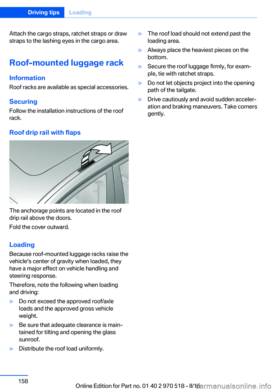
The anchorage points are located in the roof
drip rail above the doors.
Fold the cover outward.
Loading Because roof-mounted luggage racks raise the
vehicle's center of gravity when loaded, they
have a major effect on vehicle handling and
steering response.
Therefore, note the following when loading
and driving:
▷Do not exceed the approved roof/axle
loads and the approved gross vehicle
weight.▷Be sure that adequate clearance is main‐
tained for tilting and opening the glass
sunroof.▷Distribute the roof load uniformly.▷The roof load should not extend past the
loading area.▷Always place the heaviest pieces on the
bottom.▷Secure the roof luggage firmly, for exam‐
ple, tie with ratchet straps.▷Do not let objects project into the opening
path of the tailgate.▷Drive cautiously and avoid sudden acceler‐
ation and braking maneuvers. Take corners
gently.Seite 158Driving tipsLoading158
Online Edition for Part no. 01 40 2 970 518 - II/16
Page 189 of 220
Tail lamps, bulb replacement
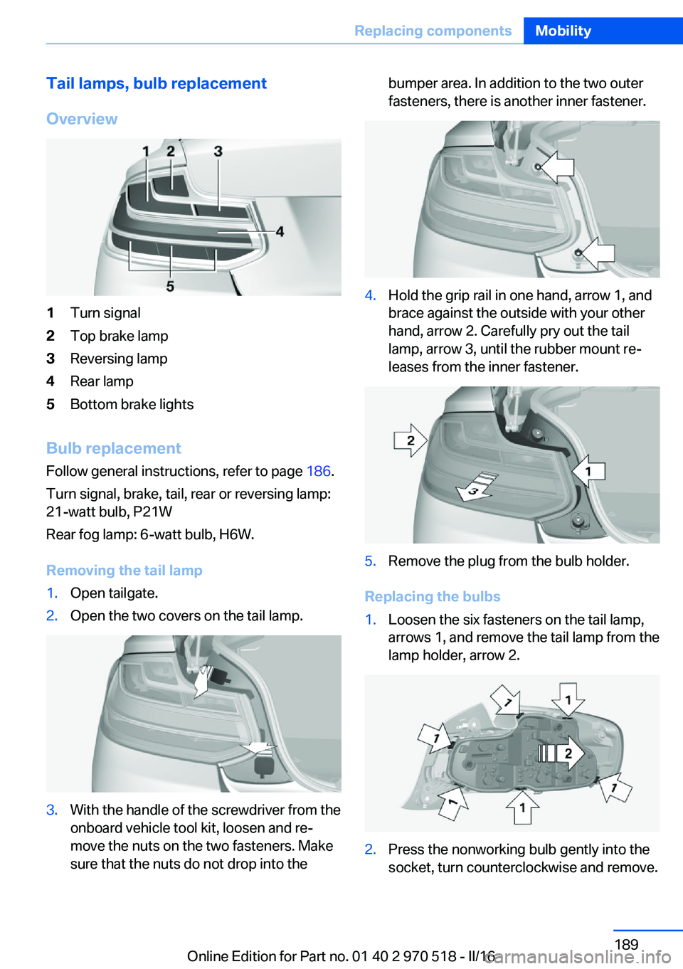
Overview1Turn signal2Top brake lamp3Reversing lamp4Rear lamp5Bottom brake lights
Bulb replacement Follow general instructions, refer to page 186.
Turn signal, brake, tail, rear or reversing lamp:
21-watt bulb, P21W
Rear fog lamp: 6-watt bulb, H6W.
Removing the tail lamp
1.Open tailgate.2.Open the two covers on the tail lamp.3.With the handle of the screwdriver from the
onboard vehicle tool kit, loosen and re‐
move the nuts on the two fasteners. Make
sure that the nuts do not drop into thebumper area. In addition to the two outer
fasteners, there is another inner fastener.4.Hold the grip rail in one hand, arrow 1, and
brace against the outside with your other
hand, arrow 2. Carefully pry out the tail
lamp, arrow 3, until the rubber mount re‐
leases from the inner fastener.5.Remove the plug from the bulb holder.
Replacing the bulbs
1.Loosen the six fasteners on the tail lamp,
arrows 1, and remove the tail lamp from the
lamp holder, arrow 2.2.Press the nonworking bulb gently into the
socket, turn counterclockwise and remove.Seite 189Replacing componentsMobility189
Online Edition for Part no. 01 40 2 970 518 - II/16
Page 194 of 220
steps to help you under certain circum‐
stances.
For this, data are transmitted to the BMW
Response Center which serve to deter‐
mine the necessary rescue measures. E.g.
the current position of the vehicle, if it can
be established.▷If the LED is flashing green, but the BMW
Response Center can no longer be heard
via the speaker, you can nevertheless still
be heard at the BMW Response Center.
Initiating an Emergency Request
automatically
Under certain conditions, an Emergency Re‐
quest is automatically initiated immediately af‐
ter a severe accident. Automatic Collision Noti‐
fication is not affected by pressing the SOS
button.
Roadside Assistance
Service availability Roadside Assistance can be reached around
the clock in many countries. You can obtain as‐
sistance there in the event of a vehicle break‐
down.
Roadside Assistance The Roadside Assistance phone number can
be viewed on the iDrive or a connection to
Roadside Assistance can be established di‐
rectly.
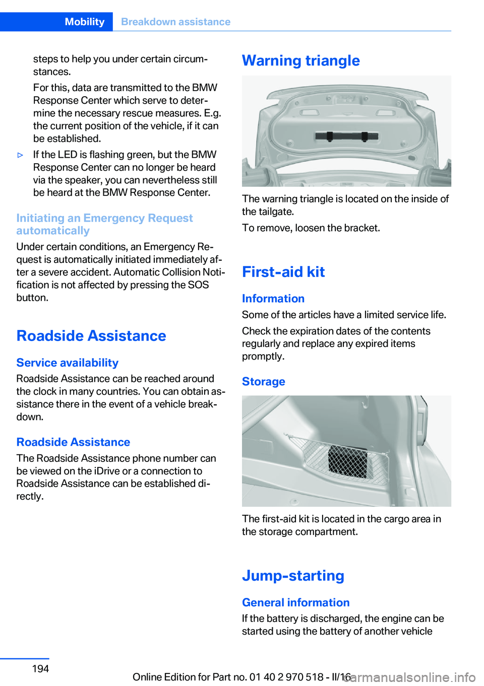
Warning triangle
The warning triangle is located on the inside of
the tailgate.
To remove, loosen the bracket.
First-aid kit InformationSome of the articles have a limited service life.
Check the expiration dates of the contents
regularly and replace any expired items
promptly.
Storage
The first-aid kit is located in the cargo area in
the storage compartment.
Jump-starting General information
If the battery is discharged, the engine can be
started using the battery of another vehicle
Seite 194MobilityBreakdown assistance194
Online Edition for Part no. 01 40 2 970 518 - II/16
Page 213 of 220
Flat Tire Monitor FTM 104
Flat tire, repairing 173
Flat tire, Tire Pressure Moni‐ tor TPM 101
Flat tire, warning lamp 102, 105
Flooding 153
Floor carpet, care 202
Floor mats, care 202
Fogged up windows 129
Fold-away position, wiper 73
Fold down the rear seat back‐ rest, see Though-loading
system 141
Foot brake 153
Front airbags 98
Front-end collision warning with City Braking func‐
tion 106
Front lights 187
Front-seat passenger airbags, automatic deactivation 100
Front-seat passenger airbags, indicator lamp 101
FTM Flat Tire Monitor 104
Fuel 166
Fuel cap 164
Fuel consumption, see Aver‐ age fuel consumption 89
Fuel filler flap 164
Fuel gauge 83
Fuel quality 166
Fuel recommendation 166
Fuel, tank capacity 207
Fuse 191
G
Garage door opener, see Uni‐ versal Integrated Remote
Control 134
Gasoline 166
Gear change 77
Gear shift indicator 86
General driving notes 153
Glare shield 138 Glass sunroof, powered 47
Glove compartment 143
GPS location, vehicle posi‐ tion 92
Gross vehicle weight, ap‐ proved 207
Ground clearance 155
H
Handbrake, see parking brake 70
Hand-held transmitter, alter‐ nating code 135
Hazard warning flashers 193
Head airbags 98
Headlamp control, auto‐ matic 94
Headlight courtesy delay fea‐ ture 94
Headlight flasher 71
Headlight glass 187
Headlights 187
Headlights, care 200
Head restraints 49
Head restraints, front 54
Head restraints, rear 55
Heavy cargo, stowing 157
High-beam Assistant 95
High beams 71
High beams/low beams, see High-beam Assistant 95
High-performance en‐ gine 150
Hills 154
Hill start assistant, see Drive- off assistant 118
Holder for beverages 145
Homepage 6
Hood 177
Horn 14
Hotel function, tailgate 41
Hot exhaust system 153
Hydroplaning 153 I
Ice warning, see External temperature warning 84
Icy roads, see External tem‐ perature warning 84
Identification marks, tires 169
Identification number, see Ve‐ hicle identification num‐
ber 10
iDrive 18
Ignition key, see Remote con‐ trol 34
Ignition off 65
Ignition on 65
Indication of a flat tire 102 , 105
Indicator and alarm lamps, see Check Control 80
Indicator lamp, see Check Control 80
Individual air distribu‐ tion 129, 131
Individual settings, see Per‐ sonal Profile 36
Inflation pressure, tires 168
Inflation pressure warning, tires 104
Info display, see On-Board computer 88
Information 6
Initialize, Tire Pressure Moni‐ tor TPM 102
Initializing, Flat Tire Monitor FTM 104
Instrument cluster 79
Instrument cluster, electronic displays 79
Instrument lighting 96
Integrated key 34
Integrated Owner's Manual in the vehicle 30
Intelligent emergency call 193
Intelligent Safety 105 Seite 213Everything from A to ZReference213
Online Edition for Part no. 01 40 2 970 518 - II/16
Page 214 of 220
Intensity, AUTO pro‐gram 131
Interior equipment 134
Interior lights 96
Interior lights during unlock‐ ing 38
Interior lights with the vehicle locked 38
Interior mirror, automatic dim‐ ming feature 59
Interior mirror, compass 136
Interior mirror, manually dim‐ mable 59
Interior motion sensor 45
Internet page 6
Interval display, service re‐ quirements 85
Interval mode 72
J Jacking points for the vehicle jack 190
Jump-starting 194
K
Key/remote control 34
Keyless Go, see Comfort Ac‐ cess 41
Key Memory, see Personal Profile 36
Knee airbag 99
L Label on recommended tires 172
Lamp replacement 186
Lamp replacement, front 187
Lamp replacement, rear 189
Lane departure warning 111
Lane margin, warning 111
Language on Control Dis‐ play 92 Lashing eyes, securing
cargo 157
LATCH child restraint fixing system 63
Launch Control 78
Leather, care 201
LEDs, light-emitting di‐ odes 187
Letters and numbers, enter‐ ing 25
Light 93
Light-alloy wheels, care 201
Light control 95
Light-emitting diodes, LEDs 187
Lighting 93
Lights and bulbs 186
Light switch 93
Load 157
Loading 156
Lock, door 39
Locking/unlocking via door lock 39
Locking/unlocking with re‐ mote control 37
Locking, automatic 43
Locking, settings 43
Locking via tailgate 41
Low beams 93
Low beams, automatic, see High-beam Assistant 95
Lower back support 51
Low Speed Assistant 75
Luggage rack, see Roof- mounted luggage rack 158
Lumbar support 51
M
Maintenance 184
Maintenance require‐ ments 184
Maintenance, service require‐ ments 85
Maintenance system, BMW 184 Make-up mirror 138
Malfunction displays, see Check Control 80
Manual air distribu‐ tion 129, 131
Manual air flow 128, 131
Manual operation, door lock 39
Manual operation, exterior mirrors 58
Manual transmission 74
Master key, see Remote con‐ trol 34
Maximum cooling 130
Maximum speed, display 86
Maximum speed, winter tires 172
M Compound brake 150
M differential, active 116
MDM, M Dynamic Mode 115
M double-clutch transmis‐ sion 75
M Dynamic Mode MDM 115
Measurement, units of 92
Medical kit 194
Memory, seat, mirror 56
Menu EfficientDynamics 85
Menu in instrument clus‐ ter 88
Menus, operating, iDrive 18
Menus, see iDrive operating concept 20
Messages, see Check Con‐ trol 80
Microfilter 129, 132
Minimum tread, tires 171
Mirror 57
Mirror memory 56
Mobile communication devi‐ ces in the vehicle 153
Mobility System 173
Modifications, technical, see Own Safety 7
Moisture in headlight 187
Monitor, see Control Dis‐ play 18 Seite 214ReferenceEverything from A to Z214
Online Edition for Part no. 01 40 2 970 518 - II/16