2016 BMW 740I SEDAN torque
[x] Cancel search: torquePage 125 of 314

Onboard computer on the
Control Display
General information
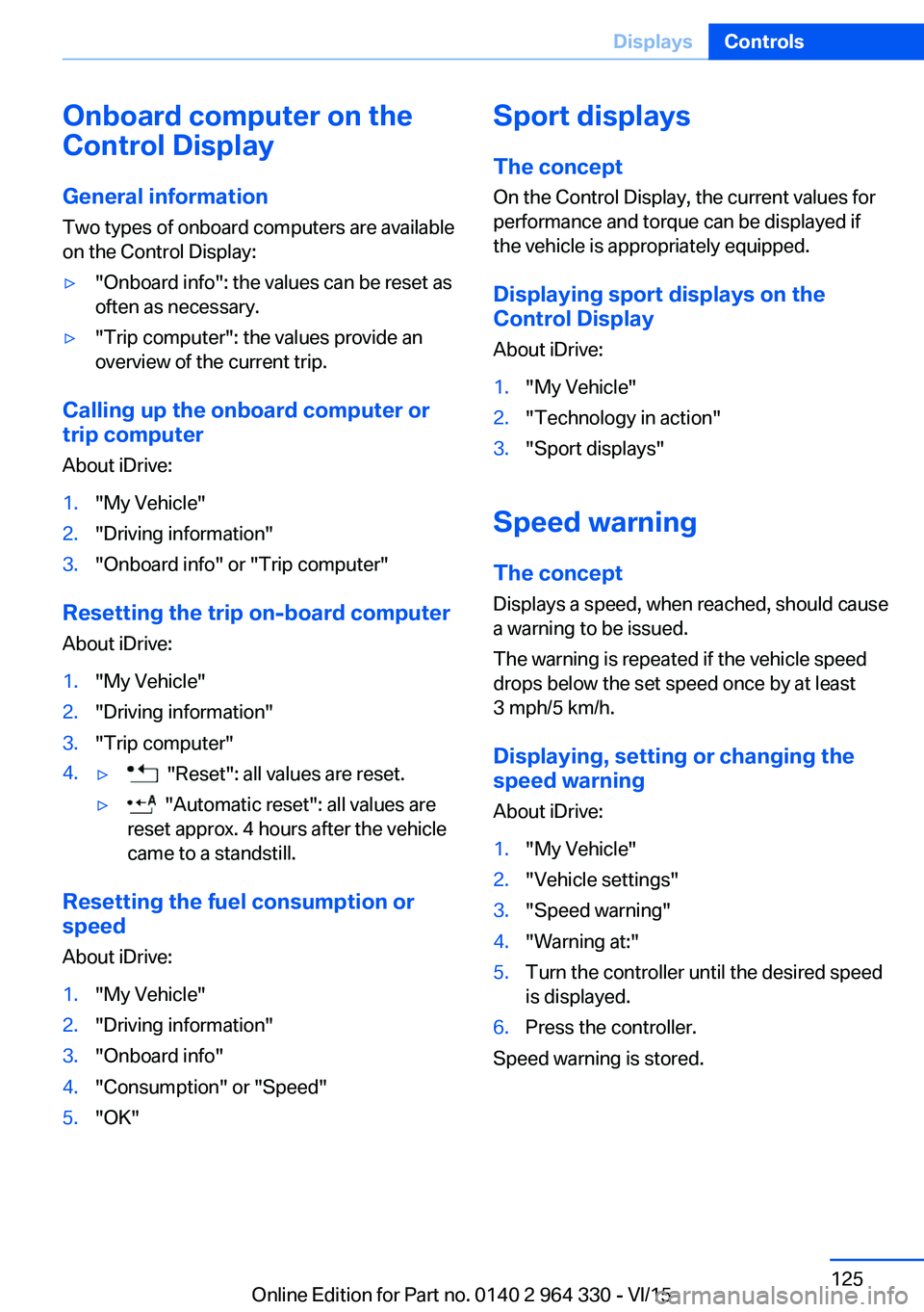
Two types of onboard computers are available
on the Control Display:▷"Onboard info": the values can be reset as
often as necessary.▷"Trip computer": the values provide an
overview of the current trip.
Calling up the onboard computer or
trip computer
About iDrive:
1."My Vehicle"2."Driving information"3."Onboard info" or "Trip computer"
Resetting the trip on-board computer
About iDrive:
1."My Vehicle"2."Driving information"3."Trip computer"4.▷ "Reset": all values are reset.▷ "Automatic reset": all values are
reset approx. 4 hours after the vehicle
came to a standstill.
Resetting the fuel consumption or
speed
About iDrive:
1."My Vehicle"2."Driving information"3."Onboard info"4."Consumption" or "Speed"5."OK"Sport displays
The concept
On the Control Display, the current values for
performance and torque can be displayed if
the vehicle is appropriately equipped.
Displaying sport displays on the
Control Display
About iDrive:1."My Vehicle"2."Technology in action"3."Sport displays"
Speed warning
The concept Displays a speed, when reached, should cause
a warning to be issued.
The warning is repeated if the vehicle speed
drops below the set speed once by at least
3 mph/5 km/h.
Displaying, setting or changing the
speed warning
About iDrive:
1."My Vehicle"2."Vehicle settings"3."Speed warning"4."Warning at:"5.Turn the controller until the desired speed
is displayed.6.Press the controller.
Speed warning is stored.
Seite 125DisplaysControls125
Online Edition for Part no. 0140 2 964 330 - VI/15
Page 284 of 314

jacking point with the entire surface on the
ground.2.Insert the vehicle jack head in the rectan‐
gular recess of the jacking point for crank‐
ing it up.3.Crank it up until the wheel in question lifts
off of the ground.
Wheel mounting
Mount one emergency wheel only.
1.Unscrew the wheel lug bolts and remove
the wheel.2.Put the new wheel or emergency wheel on
and screw in at least two bolts.
If original BMW light alloy wheels are not
mounted, any accompanying lug bolts also
have to be used.3.Screw in the remaining the lug bolts and
tighten all bolts well in a crosswise pattern.4.Lower the vehicle and remove the vehicle
jack.
After the wheel change
1.Tighten the lug bolts crosswise. The tight‐
ening torque is 101 lb ft/140 Nm.2.Stow the nonworking wheel in the trunk.
The nonworking wheel cannot be stored
under the cargo floor panel because of its
size.3.Check tire inflation pressure at the next op‐
portunity and correct as needed.4.Reinitialize the Flat Tire Monitor.Reset the Tire Pressure Monitor.5.Check to make sure the lug bolts are tight
with a calibrated torque wrench.6.Replace the damaged tires as soon as pos‐
sible.
Driving with emergency wheel
WARNING
The emergency wheel has particular di‐
mensions. When driving with an emergency
wheel, changed driving properties may occur
at higher speeds, e.g. reduced lane stability
when braking, longer braking distance and
changed self-steering properties in the limit
area. There is risk of an accident. Drive moder‐
ately and do not exceed a speed of
50 mph/80 km/h.◀
Vehicle battery Maintenance
The battery is maintenance-free.
The added amount of acid is sufficient for the
service life of the battery.
More information about the battery can be re‐
quested from a dealer’s service center or an‐
other qualified service center or repair shop.
Battery replacement CAUTION
Vehicle batteries that are not compatible
can damage vehicle systems and impair vehi‐
cle functions.There is risk of property damage.
Information on the compatible vehicle batteries
is available at your dealer's service center.◀
After a battery replacement, the manufacturer
of your vehicle recommends that the vehicle
battery be registered on the vehicle by a
dealer’s service center or another qualified
service center or repair shop to ensure that all
comfort features are fully available and that any
Seite 284MobilityReplacing components284
Online Edition for Part no. 0140 2 964 330 - VI/15
Page 310 of 314

SET button, see ActiveCruise Control, ACC 168
SET button, see Cruise con‐ trol 175
Settings, locking/unlock‐ ing 67
Settings on the Control Dis‐ play 38
Settings, storing for seat, mir‐ rors, steering wheel 87
Shift paddles on the steering wheel 106
Shoulder support front 77
Shoulder support rear 79
Side airbag 136
Side collision warning 156
Signaling, horn 14
Signals when unlocking 68
Sitting safely 76
Size 298
Ski and snowboard bag 224
Slide/tilt glass roof 73
Smoker's package 217
Snow chains 264
Socket, OBD Onboard Diag‐ nostics 280
Sockets, see Connecting electrical devices 220
Software update 46
SOS button 286
Spare fuse 285
Spare tire, see Emergency wheel 282
Speed, average 124
Speed limiter, display 120
Speed Limit Information 120
Speed warning 125
Split screen 27
Sport displays, torque dis‐ play, performance dis‐
play 125
SPORT drive mode, see Driv‐ ing Dynamics Control 110
SPORT INDIVIDUAL drive mode, see Driving Dynamics
Control 110 SPORT INDIVIDUAL, see
Driving Dynamics Con‐
trol 110
Sport program, Steptronic transmission 106
SPORT, see Driving Dynam‐ ics Control 110
Stability control systems 163
Start/stop, automatic func‐ tion 98
Start/Stop button 97
Start function during malfunc‐ tion 55
Starting, see drive readi‐ ness 97
Starting the engine, see drive readiness 97
Status control display, tires 265
Status information, iDrive 27
Status of Owner's Manual 7
Status, vehicle 126
Steering and lane guidance assistant including Traffic
Jam Assist 177
Steering, Integral Active Steering 166
Steering wheel, adjusting 87
Steering wheel heating 87
Steering wheel memory 87
Steptronic Sport transmis‐ sion, see Steptronic trans‐
mission 106
Steptronic transmission 106
Stopping the engine, see drive readiness 97
Storage compartment on the center console 226
Storage compartments 225
Storage compartments, loca‐ tions 225
Storage, tires 260
Storing the vehicle 294
Suitable engine oil types 275
Summer tires, tread 258
Sun visor 217 Supplementary text mes‐
sage 117
Surround View 187
Suspension settings 110
Switch for Dynamic Driving Control 110
Switch, see Cockpit 14
Symbols 6
Symbols in the status field 27
SYNC program, automatic cli‐ mate control 206
T Table 223
Tablet 36
Tachometer 118
Technical changes, see Own Safety 7
Technical data 298
Telephone 6
Temperature, automatic cli‐ mate control 204
Temperature display for ex‐ ternal temperature 118
Temperature, engine oil 118
Tempomat, see Active Cruise Control 168
Terminal, starting aid 288
Text message, supplemen‐ tary 117
Theft alarm system, see Alarm system 69
Thermal camera, see Night Vision 147
Through-loading system 222
Tilt alarm sensor 70
Time of arrival 124
Tire damage 258
Tire identification marks 256
Tire inflation pressure 254
Tire inflation pressure moni‐ tor, see FTM 268
Tire Pressure Monitor TPM 264
Tires, changing 258 Seite 310ReferenceEverything from A to Z310
Online Edition for Part no. 0140 2 964 330 - VI/15