2016 BMW 6 SERIES GRAN COUPE lock
[x] Cancel search: lockPage 106 of 255
Knee airbagThe knee airbag supports the legs in a frontal
impact.
Protective action
Airbags are not triggered in every impact situa‐
tion, e.g., in less severe accidents or rear-end
collisions.
Information on how to ensure the optimal
protective effect of the airbags▷Keep at a distance from the airbags.▷Always grasp the steering wheel on the
steering wheel rim, holding your hands at
the 3 o'clock and 9 o'clock positions, to
keep the risk of injury to your hands or
arms as low as possible when the airbag is
triggered.▷There should be no person, animals, or ob‐
jects between an airbag and a person.▷Do not use the cover of the front airbag on
the front passenger side as a storage area.▷Dashboard and windshield on the front
passenger side must stay clear - do not at‐
tach adhesive labels or coverings and do
not attach brackets or cables, e. g., for GPS
devices or' mobile phones.▷Make sure that the front passenger is sit‐
ting correctly, i.e., keeps his or her feet and
legs in the footwell; otherwise, leg injuries
might occur when front airbag is activated.▷Do not place slip covers, seat cushions or
other objects on the front passenger seat
that are not approved specifically for seats
with integrated side airbags.▷Do not hang pieces of clothing, such as
jackets, over the backrests.▷Make sure that occupants keep their heads
away from the side airbag and do not rest
against the head airbag; otherwise, injuries
might occur when airbag is activated.▷Do not remove the airbag system.▷Do not remove the steering wheel.▷Do not apply adhesive materials to the air‐
bag cover panels, do not cover them or
modify them in any way.▷Never modify either the individual compo‐
nents or the wiring in the airbag system.
This also applies to steering wheel covers,
the dashboard, the seats, the roof pillars
and the sides of the roofliner.◀
Even when you follow all instructions very
closely, injury from contact with the airbags
cannot be ruled out in certain situations.
The ignition and inflation noise may lead to
short-term and, in most cases, temporary
hearing impairment in sensitive individuals.
Malfunction, deactivation and after de‐
ploying the airbags
Do not touch the individual components imme‐
diately after the system has been triggered;
otherwise, you may risk burns.
Only have the airbags checked, repaired or dis‐
mantled and the airbag generator scrapped by
the service center or an authorized repair shop
for handling explosives.
Non-professional attempts to service the sys‐
tem could lead to failure in an emergency or
unintentional activation of the airbag - both
may lead to injury.◀
Warnings and information on the airbags are also found on the sun visors.
Functional readiness of the airbag
system
When the ignition is reel on, the warn‐
ing lamp in the instrument cluster lights
up briefly and thereby indicates the op‐
erational readiness of the entire airbag system
and the belt tensioner.
Airbag system malfunctioning
▷Warning lamp does not come on when the
ignition is turned on.▷The warning lamp lights up continuously.Seite 102ControlsSafety102
Online Edition for Part no. 01 40 2 954 231 - II/15
Page 130 of 255
▷PreCrash▷PostCrash
Attentiveness assistant
The concept The system can detect increasing lack of alert‐
ness or fatigue of the driver during long, mo‐
notonous journeys, e.g., on highways. In this situation, it is recommended that the driver
takes a break.
Note Personal responsibility
The system cannot act as a substitute for
the personal assessment of one's physical
state and may not detect an increasing lack of
alertness or fatigue or may not detect it cor‐
rectly. Therefore, make sure that the driver is
rested and alert; otherwise, risks may be de‐
tected too late and an accident be caused as a
result.◀
Function
The system is activated each time the engine
is started and cannot be switched off.
After travel has begun, the system is trained
about the driver, so that increasing lack of
alertness or fatigue can be detected.
This procedure takes the following criteria into
account:
▷Personal driving style, e.g., steering behav‐
ior.▷Driving conditions, e.g., length of trip.
Starting at approximately 43 mph/70 km/h, the
system is active and can display a recommen‐
dation to take a break.
Break recommendation
If the driver becomes increasingly less alert or
fatigued, a message is displayed in the Control
Display with the recommendation to take a
break.
A recommendation to take a break is displayed
only once during an uninterrupted trip.
After a break, another recommendation to take
a break cannot be displayed until after approxi‐
mately 45 minutes.
System limits
The function may be limited in the following
situations, for instance, and will either output
an incorrect warning or no warning at all:▷When the clock is set incorrectly.▷When the vehicle speed is mainly below
about 43 mph/70 km/h.▷With a sporty driving style, such as during
rapid acceleration or when cornering fast.▷In active driving situations, such as when
changing lanes frequently.▷When the road surface is poor.▷In the event of strong side winds.
PreCrash
The concept With this system critical driving situations that
might result in an accident can be detected
above a speed of approx. 20 mph/30 km/h. In these situations, preventive measures are au‐
tomatically taken to minimize the risk of an ac‐
cident as much as possible.
Critical driving situations may include:
Emergency stop.
If the vehicle includes the front-end collision
warning or front-end collision warning with
braking feature, impending collisions with vehi‐
cles driving ahead or stopped in front of you
can also be detected within the system's
range.
Seite 126ControlsSafety126
Online Edition for Part no. 01 40 2 954 231 - II/15
Page 132 of 255
Driving stability control systemsVehicle features and optionsThis chapter describes all standard, country-
specific and optional features offered with the
series. It also describes features that are not
necessarily available in your car, e. g., due to
the selected options or country versions. This
also applies to safety-related functions and
systems. The respectively applicable country
provisions must be observed when using the
respective features and systems.
Antilock Brake System ABS ABS prevents locking of the wheels during
braking.
The vehicle contains its steering power even
during full brake applications, thus increasing
active safety.
ABS is operational every time you start the en‐
gine.
Brake assistant When you apply the brakes rapidly, this system
automatically produces the greatest possible
braking force boost. It reduces the braking dis‐
tance to a minimum during emergency stop.
This system utilizes all of the benefits provided
by ABS.
Do not reduce the pressure on the brake pedal
for the duration of the emergency stop.
Adaptive brake assistant In combination with the Active Cruise Control,
this system ensures that the brakes respond
even more rapidly when braking in critical sit‐
uations.Drive-off assistant
This system supports driving off on inclines.
The parking brake is not required.1.Hold the vehicle in place with the foot
brake.2.Release the foot brake and drive off with‐
out delay.
After the foot brake is released, the vehicle is
held in place for approx. 2 seconds.
Depending on the vehicle load, the vehicle may
roll back slightly.
Driving off without delay
After releasing the foot brake, start driv‐
ing without delay, since the drive-off assistant
will not hold the vehicle in place for more than
approx. 2 seconds and the vehicle will begin to
roll back.◀
DSC Dynamic Stability
Control
The concept DSC prevents traction loss in the power
wheels when driving off and accelerating.
DSC also recognizes unstable vehicle condi‐
tions such as fishtailing or nose-diving. Within
the physical limits DSC helps to keep the vehi‐
cle on a steady course by reducing engine
speed and by applying brakes to the individual
wheels.
Note Adjust your driving style to the situation
An appropriate driving style is always the
responsibility of the driver.
The laws of physics cannot be repealed, not
even with DSC.
Seite 128ControlsDriving stability control systems128
Online Edition for Part no. 01 40 2 954 231 - II/15
Page 163 of 255

Ice and condensation are quickly removed
from the windshield and the front side win‐
dows.
For this purpose, point the side vents onto the
side windows as needed.
Adjust air flow with the program active.
If the windows are fogged over, you can also
switch on the cooling function or press the
AUTO button to utilize the condensation sen‐
sor.
Maximum cooling Press button.
The system is set to the lowest tem‐
perature, optimum air flow and air circulation mode.
Air flows out of the vents to the upper body re‐
gion. The vents need to be open for this.
The function is available above an external
temperature of approx. 32 ℉/0 ℃ and with the
engine running is indicated.
Adjust air flow with the program active.
Automatic recirculated-air control/
recirculated-air mode
You may respond to unpleasant odors or pollu‐
tants in the immediate environment by tempo‐
rarily suspending the supply of outside air. The
system then recirculates the air currently
within the vehicle.
Press button repeatedly to select an
operating mode:▷LEDs off: outside air flows in continuously.▷Left LED on, automatic recirculated-air
control: a sensor detects pollutants in the
outside air and shuts off automatically.▷Right LED on, recirculated-air mode: the
supply of outside air into the vehicle is per‐
manently blocked.
If the windows are fogged over, switch off the
recirculated-air mode and press the AUTO
button on the driver's side to utilize the con‐
densation sensor. Make sure that air can flow
to the windshield.
Sufficient ventilation
When remaining in the vehicle for an ex‐
tended period of time, ensure sufficient exter‐
nal ventilation. Do not continuously use recir‐
culated-air mode; otherwise the air quality in
the interior continuously deteriorates and win‐
dow condensation increases.◀
Cooling function The car's interior can only be cooled with the
engine running.
Press button.
The air will be cooled and dehumidi‐
fied and, depending on the temperature set‐
ting, warmed again.
Depending on the weather, the windshield and
side windows may fog up briefly when the en‐
gine is started.
The cooling function is switched on automati‐
cally with the AUTO program.
When using the automatic climate control,
condensation water, refer to page 180, devel‐
ops that exits underneath the vehicle.
Rear window defroster Press button.
The rear window defroster switches
off automatically after a certain period of time.
SYNC program The current settings on the driver's
side for temperature, air flow, air distri‐
bution, and AUTO program are transferred to the front passenger side and to the left and
right rear.
The program is switched off if the settings on
the front passenger side or in the rear are
changed.Seite 159Climate controlControls159
Online Edition for Part no. 01 40 2 954 231 - II/15
Page 173 of 255
Center armrest
Remove the cover.
Through-loading system The concept The cargo area can be enlarged by folding
down the rear seat backrest.
The rear seat backrest is divided into two parts
at a ratio of 60 to 40.
The sides can be folded down separately or to‐
gether.
Hints Danger of jamming
Before folding down the rear seat back‐
rests, ensure that the area of movement of the backrests is clear. Ensure that no one is lo‐
cated in or reaches into the area of movement
of the rear seat backrests. Otherwise, injury or
damage may result.◀
Ensuring the stability of the child seat
When installing child restraint systems,
make sure that the child seat is securely fas‐
tened to the backrest of the seat. Angle and
headrest of the backrest might need to be ad‐
justed or possibly be removed. Make sure that
all backrests are securely locked. Otherwise
the stability of the child seat can be affected,
and there is an increased risk of injury because
of unexpected movement of the seat back‐ rest.◀
Preventing indentations
When folding down the rear seats, en‐
sure that the safety belt buckles are located in
the recesses provided form them in the seat.
Otherwise they can create indentations in the
backrest.◀
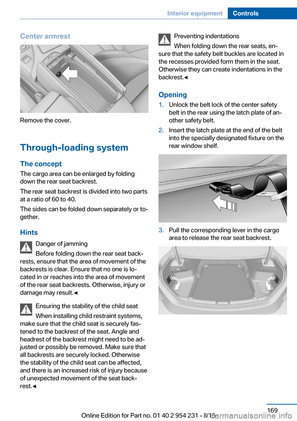
Opening1.Unlock the belt lock of the center safety
belt in the rear using the latch plate of an‐
other safety belt.2.Insert the latch plate at the end of the belt
into the specially designated fixture on the
rear window shelf.3.Pull the corresponding lever in the cargo
area to release the rear seat backrest.Seite 169Interior equipmentControls169
Online Edition for Part no. 01 40 2 954 231 - II/15
Page 174 of 255
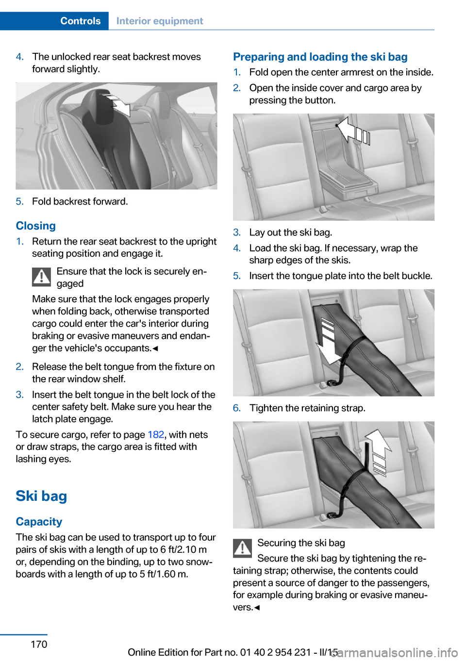
4.The unlocked rear seat backrest moves
forward slightly.5.Fold backrest forward.
Closing
1.Return the rear seat backrest to the upright
seating position and engage it.
Ensure that the lock is securely en‐
gaged
Make sure that the lock engages properly
when folding back, otherwise transported
cargo could enter the car's interior during
braking or evasive maneuvers and endan‐
ger the vehicle's occupants.◀2.Release the belt tongue from the fixture on
the rear window shelf.3.Insert the belt tongue in the belt lock of the
center safety belt. Make sure you hear the
latch plate engage.
To secure cargo, refer to page 182, with nets
or draw straps, the cargo area is fitted with
lashing eyes.
Ski bag
Capacity
The ski bag can be used to transport up to four
pairs of skis with a length of up to 6 ft/2.10 m
or, depending on the binding, up to two snow‐
boards with a length of up to 5 ft/1.60 m.
Preparing and loading the ski bag1.Fold open the center armrest on the inside.2.Open the inside cover and cargo area by
pressing the button.3.Lay out the ski bag.4.Load the ski bag. If necessary, wrap the
sharp edges of the skis.5.Insert the tongue plate into the belt buckle.6.Tighten the retaining strap.
Securing the ski bag
Secure the ski bag by tightening the re‐
taining strap; otherwise, the contents could
present a source of danger to the passengers,
for example during braking or evasive maneu‐
vers.◀
Seite 170ControlsInterior equipment170
Online Edition for Part no. 01 40 2 954 231 - II/15
Page 177 of 255
▷Do not use force when plugging the con‐
nector into the USB interface.▷Do not connect devices such as fans or
lights to the USB interface.▷Do not connect USB hard drives.▷Do not use the USB interface for recharg‐
ing external devices.
With navigation system Professional
or TV: at a glance
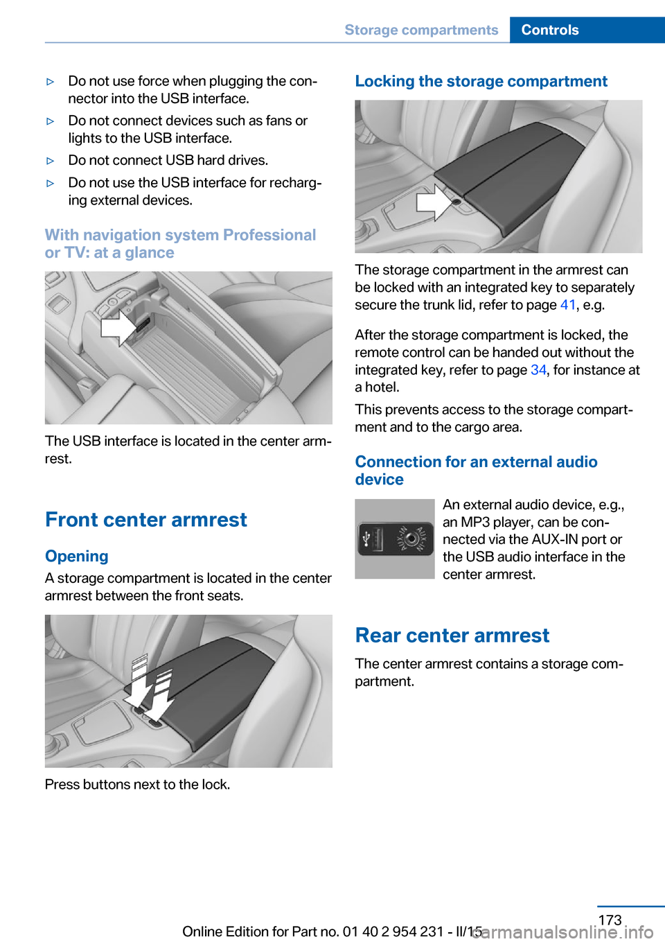
The USB interface is located in the center arm‐
rest.
Front center armrest Opening
A storage compartment is located in the center
armrest between the front seats.
Press buttons next to the lock.
Locking the storage compartment
The storage compartment in the armrest can
be locked with an integrated key to separately
secure the trunk lid, refer to page 41, e.g.
After the storage compartment is locked, the
remote control can be handed out without the
integrated key, refer to page 34, for instance at
a hotel.
This prevents access to the storage compart‐
ment and to the cargo area.
Connection for an external audio
device
An external audio device, e.g.,
an MP3 player, can be con‐
nected via the AUX-IN port or
the USB audio interface in the center armrest.
Rear center armrest The center armrest contains a storage com‐
partment.
Seite 173Storage compartmentsControls173
Online Edition for Part no. 01 40 2 954 231 - II/15
Page 196 of 255
RefuelingVehicle features and options
This chapter describes all standard, country-
specific and optional features offered with the
series. It also describes features that are not
necessarily available in your car, e. g., due to
the selected options or country versions. This
also applies to safety-related functions and
systems. The respectively applicable country
provisions must be observed when using the
respective features and systems.
Hints Observe the fuel recommendation, refer to
page 194, prior to refueling.
Refuel promptly
Refuel no later than at a range of
30 miles/50 km or engine operation might fail
and damage might occur.◀
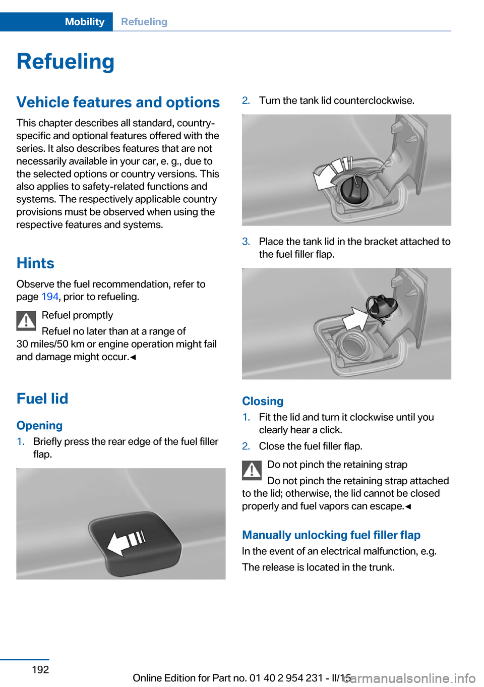
Fuel lid Opening1.Briefly press the rear edge of the fuel filler
flap.2.Turn the tank lid counterclockwise.3.Place the tank lid in the bracket attached to
the fuel filler flap.
Closing
1.Fit the lid and turn it clockwise until you
clearly hear a click.2.Close the fuel filler flap.
Do not pinch the retaining strap
Do not pinch the retaining strap attached
to the lid; otherwise, the lid cannot be closed
properly and fuel vapors can escape.◀
Manually unlocking fuel filler flap In the event of an electrical malfunction, e.g.
The release is located in the trunk.
Seite 192MobilityRefueling192
Online Edition for Part no. 01 40 2 954 231 - II/15