2016 BMW 6 SERIES GRAN COUPE flat tire
[x] Cancel search: flat tirePage 207 of 255
Traction
The traction grades, from highest to lowest,
are AA, A, B, and C.
Those grades represent the tire's ability to
stop on wet pavement as measured under
controlled conditions on specified government
test surfaces of asphalt and concrete. A tire
marked C may have poor traction performance.
The traction grade assigned to this tire is
based on straight-ahead braking traction tests,
and does not include acceleration, cornering,
hydroplaning, or peak traction characteristics.
Temperature
The temperature grades are A, the highest, B,
and C, representing the tire's resistance to the
generation of heat and its ability to dissipate
heat when tested under controlled conditions
on a specified indoor laboratory test wheel.
Sustained high temperature can cause the ma‐
terial of the tire to degenerate and reduce tire
life, and excessive temperature can lead to
sudden tire failure. The grade C corresponds
to a level of performance which all passenger
car tires must meet under the Federal Motor
Vehicle Safety Standard No. 109. Grades Band
A represent higher levels of performance on
the laboratory test wheel than the minimum re‐
quired by law.
Temperature grade for this tire
The temperature grade for this tire is es‐
tablished for a tire that is properly inflated and
not overloaded. Excessive speed, underinfla‐
tion, or excessive loading, either separately or
in combination, can cause heat buildup and
possible tire failure.
If necessary, have the vehicle towed.◀
RSC – Run-flat tires
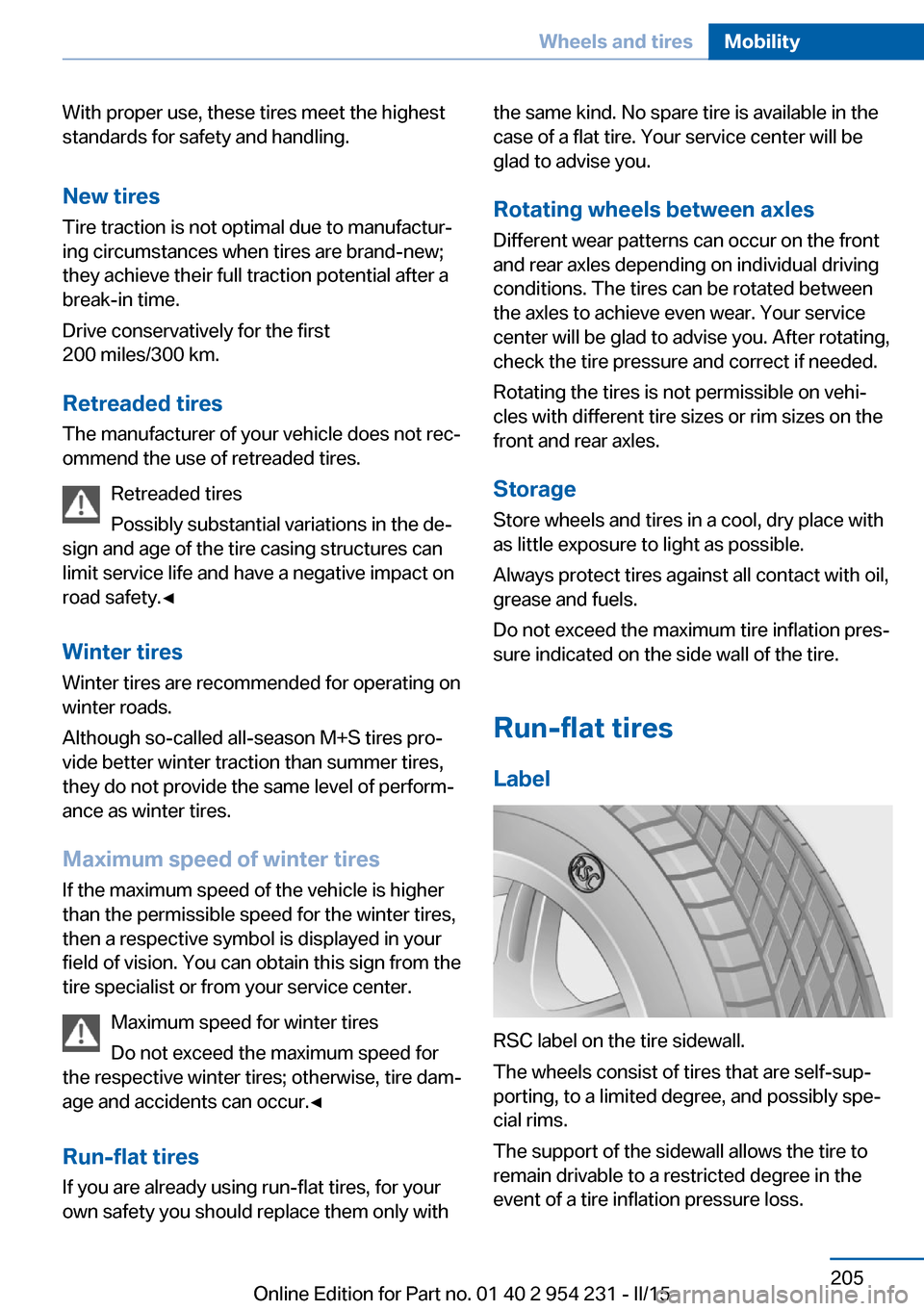
Run-flat tires, refer to page 205, are labeled
with a circular symbol containing the letters
RSC marked on the sidewall.M+S
Winter and all-season tires with better cold
weather performance than summer tires.
Tire tread Summer tires
Do not drive with a tire tread depth of less than
0.12 in/3 mm.
There is an increased danger of hydroplaning if
the tire tread depth is less than 0.12 in/3 mm.
Winter tires
Do not drive with a tire tread depth of less than
0.16 in/4 mm.
Below a tread depth of 0.16 in/4 mm, tires are
less suitable for winter operation.
Minimum tread depth
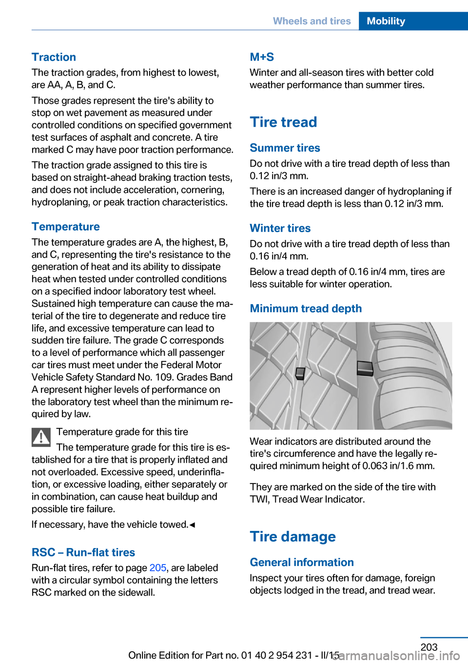
Wear indicators are distributed around the
tire's circumference and have the legally re‐
quired minimum height of 0.063 in/1.6 mm.
They are marked on the side of the tire with
TWI, Tread Wear Indicator.
Tire damage
General information
Inspect your tires often for damage, foreign
objects lodged in the tread, and tread wear.
Seite 203Wheels and tiresMobility203
Online Edition for Part no. 01 40 2 954 231 - II/15
Page 209 of 255
With proper use, these tires meet the highest
standards for safety and handling.
New tires Tire traction is not optimal due to manufactur‐
ing circumstances when tires are brand-new;
they achieve their full traction potential after a
break-in time.
Drive conservatively for the first
200 miles/300 km.
Retreaded tires
The manufacturer of your vehicle does not rec‐
ommend the use of retreaded tires.
Retreaded tires
Possibly substantial variations in the de‐
sign and age of the tire casing structures can
limit service life and have a negative impact on
road safety.◀
Winter tires
Winter tires are recommended for operating on
winter roads.
Although so-called all-season M+S tires pro‐
vide better winter traction than summer tires,
they do not provide the same level of perform‐
ance as winter tires.
Maximum speed of winter tires
If the maximum speed of the vehicle is higher
than the permissible speed for the winter tires,
then a respective symbol is displayed in your
field of vision. You can obtain this sign from the
tire specialist or from your service center.
Maximum speed for winter tires
Do not exceed the maximum speed for
the respective winter tires; otherwise, tire dam‐
age and accidents can occur.◀
Run-flat tiresIf you are already using run-flat tires, for your
own safety you should replace them only withthe same kind. No spare tire is available in the
case of a flat tire. Your service center will be
glad to advise you.
Rotating wheels between axles Different wear patterns can occur on the front
and rear axles depending on individual driving
conditions. The tires can be rotated between
the axles to achieve even wear. Your service
center will be glad to advise you. After rotating,
check the tire pressure and correct if needed.
Rotating the tires is not permissible on vehi‐
cles with different tire sizes or rim sizes on the
front and rear axles.
StorageStore wheels and tires in a cool, dry place with
as little exposure to light as possible.
Always protect tires against all contact with oil,
grease and fuels.
Do not exceed the maximum tire inflation pres‐
sure indicated on the side wall of the tire.
Run-flat tires Label
RSC label on the tire sidewall.
The wheels consist of tires that are self-sup‐
porting, to a limited degree, and possibly spe‐
cial rims.
The support of the sidewall allows the tire to
remain drivable to a restricted degree in the
event of a tire inflation pressure loss.
Seite 205Wheels and tiresMobility205
Online Edition for Part no. 01 40 2 954 231 - II/15
Page 210 of 255
Follow the instructions for continued driving
with a flat tire.
Changing run-flat tires
For your own safety, only use run-flat tires. No
spare tire is available in the case of a flat tire.
Your service center will be glad to advise you.
Mobility System
The concept With the Mobility System, minor tire damagecan be sealed quickly to enable continued
travel. To accomplish this, sealant is pumped
into the tires, which seals the damage from the inside.
The compressor can be used to check the tire
inflation pressure.
Hints▷Follow the instructions on using the Mobi‐
lity System found on the compressor and
sealant container.▷Use of the Mobility System may be ineffec‐
tive if the tire puncture measures approx.
1/8 in/4 mm or more.▷Contact the nearest service center if the
tire cannot be made drivable.▷If possible, do not remove foreign bodies
that have penetrated the tire.▷Pull the speed limit sticker off the sealant
container and apply it to the steering
wheel.▷The use of a sealant can damage the TPM
wheel electronics. In this case, have the
electronics checked at the next opportu‐
nity and have them replaced if needed.
Enclosed areas
Do not let the engine run in enclosed
areas, since breathing in exhaust fumes may
lead to loss of consciousness and death. The
exhaust gases contain carbon monoxide, an
odorless and colorless but highly toxic gas.◀
Storage The Mobility System is located under the
cargo floor panel.
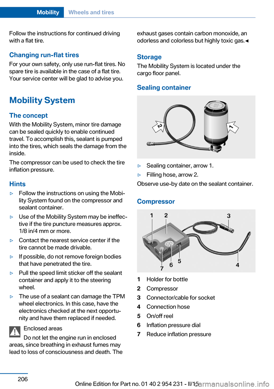
Sealing container▷Sealing container, arrow 1.▷Filling hose, arrow 2.
Observe use-by date on the sealant container.
Compressor
1Holder for bottle2Compressor3Connector/cable for socket4Connection hose5On/off reel6Inflation pressure dial7Reduce inflation pressureSeite 206MobilityWheels and tires206
Online Edition for Part no. 01 40 2 954 231 - II/15
Page 212 of 255
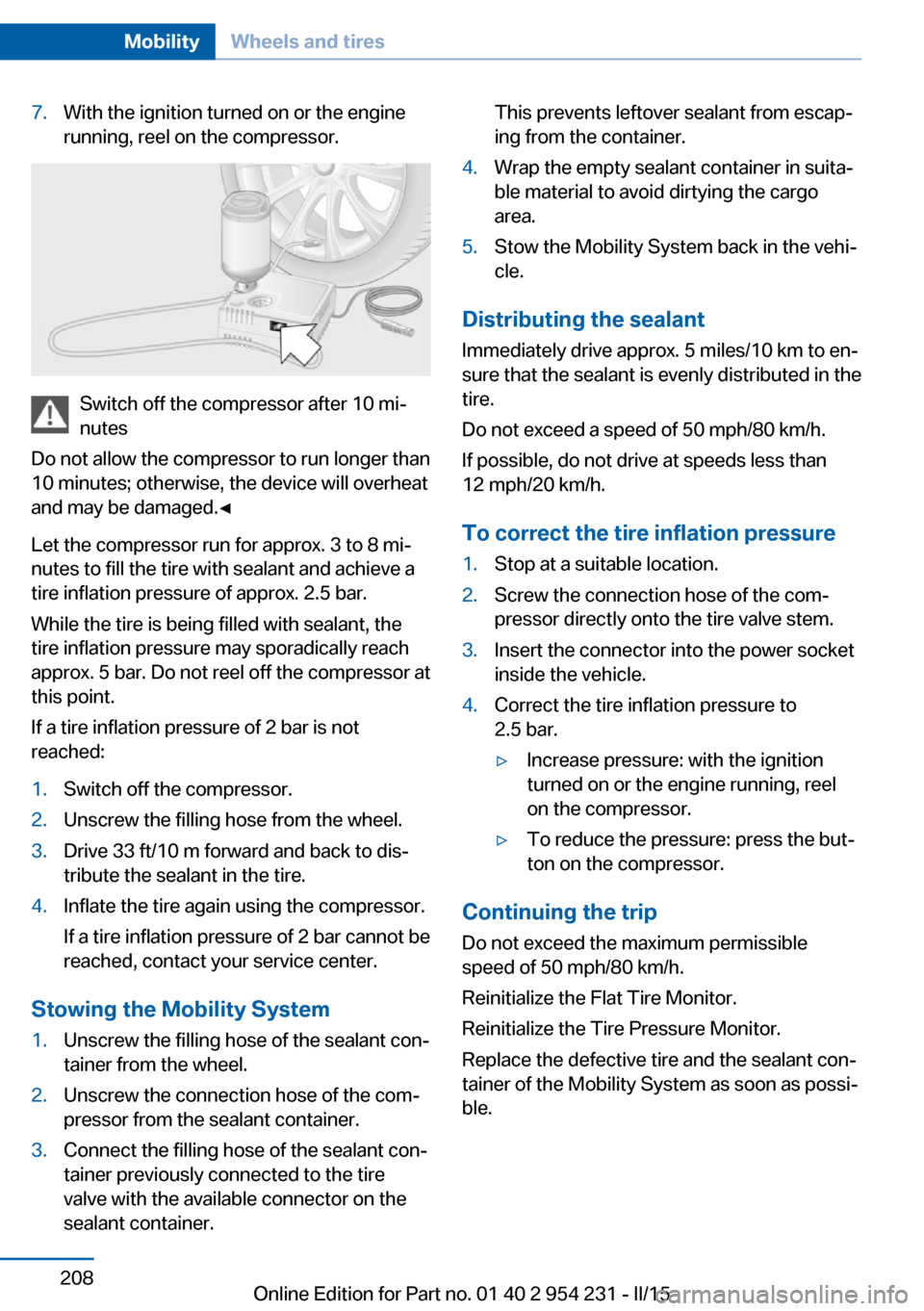
7.With the ignition turned on or the engine
running, reel on the compressor.
Switch off the compressor after 10 mi‐
nutes
Do not allow the compressor to run longer than
10 minutes; otherwise, the device will overheat
and may be damaged.◀
Let the compressor run for approx. 3 to 8 mi‐
nutes to fill the tire with sealant and achieve a
tire inflation pressure of approx. 2.5 bar.
While the tire is being filled with sealant, the
tire inflation pressure may sporadically reach
approx. 5 bar. Do not reel off the compressor at
this point.
If a tire inflation pressure of 2 bar is not
reached:
1.Switch off the compressor.2.Unscrew the filling hose from the wheel.3.Drive 33 ft/10 m forward and back to dis‐
tribute the sealant in the tire.4.Inflate the tire again using the compressor.
If a tire inflation pressure of 2 bar cannot be
reached, contact your service center.
Stowing the Mobility System
1.Unscrew the filling hose of the sealant con‐
tainer from the wheel.2.Unscrew the connection hose of the com‐
pressor from the sealant container.3.Connect the filling hose of the sealant con‐
tainer previously connected to the tire
valve with the available connector on the
sealant container.This prevents leftover sealant from escap‐
ing from the container.4.Wrap the empty sealant container in suita‐
ble material to avoid dirtying the cargo
area.5.Stow the Mobility System back in the vehi‐
cle.
Distributing the sealant
Immediately drive approx. 5 miles/10 km to en‐
sure that the sealant is evenly distributed in the
tire.
Do not exceed a speed of 50 mph/80 km/h.
If possible, do not drive at speeds less than
12 mph/20 km/h.
To correct the tire inflation pressure
1.Stop at a suitable location.2.Screw the connection hose of the com‐
pressor directly onto the tire valve stem.3.Insert the connector into the power socket
inside the vehicle.4.Correct the tire inflation pressure to
2.5 bar.▷Increase pressure: with the ignition
turned on or the engine running, reel
on the compressor.▷To reduce the pressure: press the but‐
ton on the compressor.
Continuing the trip
Do not exceed the maximum permissible
speed of 50 mph/80 km/h.
Reinitialize the Flat Tire Monitor.
Reinitialize the Tire Pressure Monitor.
Replace the defective tire and the sealant con‐
tainer of the Mobility System as soon as possi‐
ble.
Seite 208MobilityWheels and tires208
Online Edition for Part no. 01 40 2 954 231 - II/15
Page 213 of 255
Snow chains
Fine-link snow chains Only certain types of fine-link snow chains
have been tested by the manufacturer of the
vehicle, classified as road-safe and approved.
Information about the approved snow chains
are available from the service center.
Use Use only in pairs on the rear wheels, equipped
with the tires of the following size:▷225/55 R 17.▷245/45 R 18.▷245/40 R 19.
Follow the snow chain manufacturer's instruc‐
tions.
Make sure that the snow chains are always
sufficiently tight. Retighten as needed accord‐
ing to the chain manufacturer's instructions.
Do not initialize the Flat Tire Monitor after
mounting snow chains, as doing so may result
in incorrect readings.
Do not initialize the Tire Pressure Monitor after
mounting snow chains, as doing so may result
in incorrect readings.
When driving with snow chains, briefly activate
Dynamic Traction Control if needed.
Maximum speed with snow chains Do not exceed a speed of 30 mph/50 km/hwhen using snow chains.
Snow chain detection
The concept When using snow chains, settings should bemade via the iDrive for the snow chains being
applied.
The snow chain detection system supports
you by automatically showing the detected
state on the Control Display.
When snow chains are in use, the rear axle
steering of the Integral Active Steering is deac‐
tivated automatically.
At speeds above the maximum permitted
speed with snow chains of 30 mph/50 km/h,
the rear axle steering is activated again auto‐
matically.
Activating the status1."Settings"2."Tire chains"3."Tire chains installed"
Automatic detection If functioning properly:
▷Snow chains are mounted. Settings are not
activated
.
After you drive a short distance, a Check
Control message is shown and the state is
activated automatically.
Confirm the automatic activation.
▷Snow chains are not mounted. Settings are
activated
.
At speeds above 30 mph/50 km/h, a Check
Control message is displayed. Deactivate
the status manually.
If not functioning properly:
▷Snow chains are mounted. Settings are not
activated
.
A Check Control message is not displayed.
The automatic detection system is mal‐
functioning. Activate the status manually.
Activating/deactivating rear axle
steering
If the status indicating that snow chains are in
use is activated, the rear axle steering is deac‐
tivated automatically.
At speeds above 30 mph/50 km/h, the rear axle
steering is activated again, even though snow
chains are in use.
Seite 209Wheels and tiresMobility209
Online Edition for Part no. 01 40 2 954 231 - II/15
Page 226 of 255
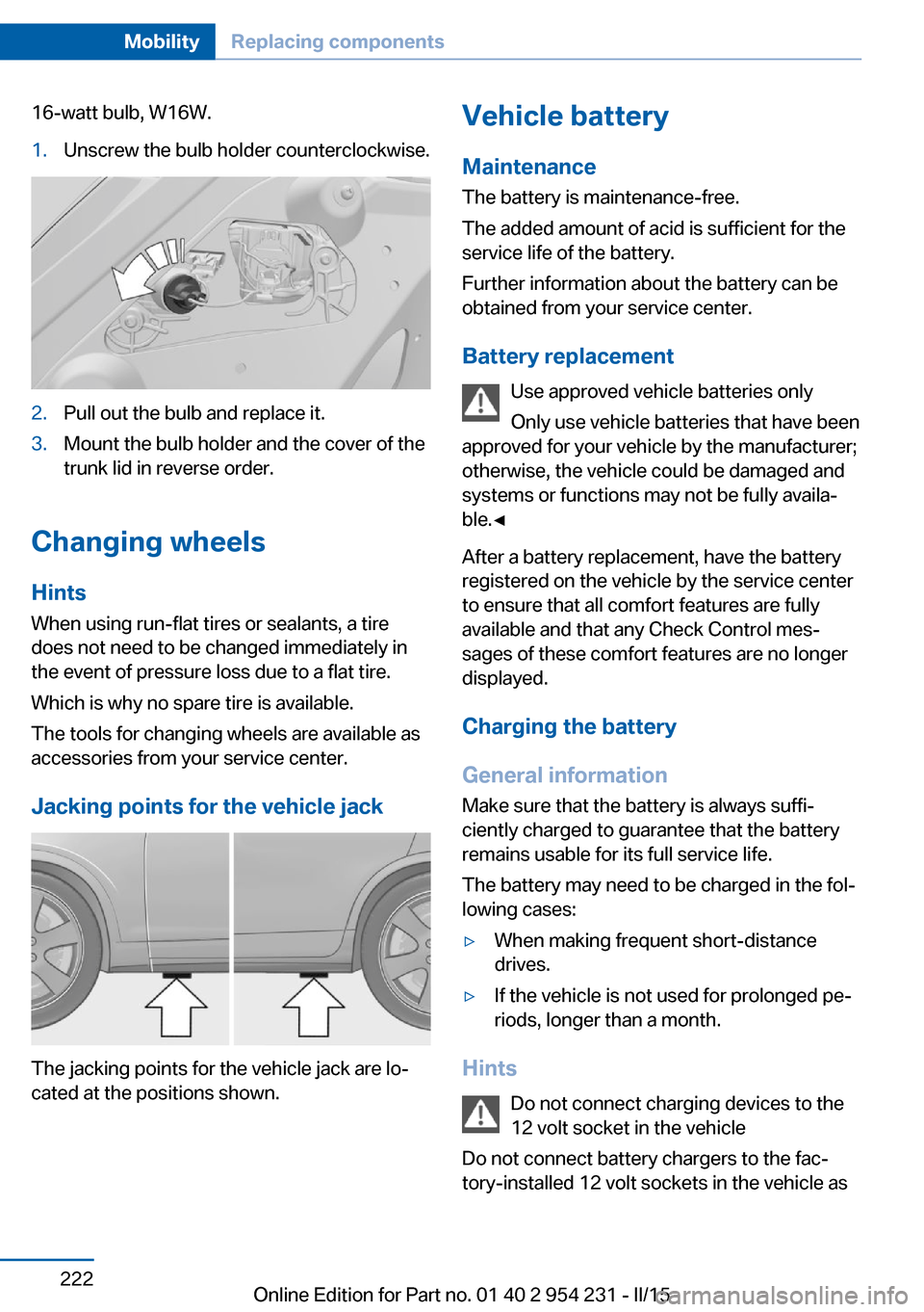
16-watt bulb, W16W.1.Unscrew the bulb holder counterclockwise.2.Pull out the bulb and replace it.3.Mount the bulb holder and the cover of the
trunk lid in reverse order.
Changing wheels
Hints
When using run-flat tires or sealants, a tire
does not need to be changed immediately in
the event of pressure loss due to a flat tire.
Which is why no spare tire is available.
The tools for changing wheels are available as
accessories from your service center.
Jacking points for the vehicle jack
The jacking points for the vehicle jack are lo‐
cated at the positions shown.
Vehicle battery
Maintenance
The battery is maintenance-free.
The added amount of acid is sufficient for the
service life of the battery.
Further information about the battery can be
obtained from your service center.
Battery replacement Use approved vehicle batteries only
Only use vehicle batteries that have been
approved for your vehicle by the manufacturer;
otherwise, the vehicle could be damaged and
systems or functions may not be fully availa‐
ble.◀
After a battery replacement, have the battery
registered on the vehicle by the service center
to ensure that all comfort features are fully
available and that any Check Control mes‐
sages of these comfort features are no longer
displayed.
Charging the battery
General information Make sure that the battery is always suffi‐
ciently charged to guarantee that the battery
remains usable for its full service life.
The battery may need to be charged in the fol‐
lowing cases:▷When making frequent short-distance
drives.▷If the vehicle is not used for prolonged pe‐
riods, longer than a month.
Hints
Do not connect charging devices to the
12 volt socket in the vehicle
Do not connect battery chargers to the fac‐
tory-installed 12 volt sockets in the vehicle as
Seite 222MobilityReplacing components222
Online Edition for Part no. 01 40 2 954 231 - II/15
Page 246 of 255

Condensation on win‐dows 158
Condensation under the vehi‐ cle 180
Condition Based Service CBS 217
Configure driving mode 135
Confirmation signal 43
ConnectedDrive, see user's manual for Navigation, En‐
tertainment and Communi‐
cation
ConnectedDrive Services
Continued driving with a flat tire 106 , 109
Control Display 18
Control Display, settings 92
Controller 18
Control systems, driving sta‐ bility 128
Convenient opening with the remote control 37
Coolant 215
Coolant level 215
Coolant temperature 85
Cooling function 159
Cooling, maximum 159
Cooling system 215
Cornering light 97
Corrosion on brake discs 180
Cosmetic mirror 167
Courtesy lamps during un‐ locking 37
Courtesy lamps with the vehi‐ cle locked 38
Cruise control 143
Cruise control, active with Stop & Go 136
Cruise Control, refer to Active Cruise Control 136
Cruising range 86
Cupholder 174
Current fuel consumption 86 D
Damage, tires 203
Damping control, dy‐ namic 131
Data, technical 236
Date 86
Daytime running lights 97
Defrosting, refer to Windows, defrosting 158
Dehumidifying, air 159
Deleting personal data 24
Deletion of personal data 24
Destination distance 91
Digital clock 86
Dimensions 236
Dimmable exterior mirrors 58
Dimmable interior rearview mirror 58
Direction indicator, refer to Turn signals 70
Display, electronic, instru‐ ment cluster 77
Display in windshield 93
Display lighting, refer to In‐ strument lighting 99
Displays 78
Displays, cleaning 232
Disposal, coolant 216
Disposal, vehicle battery 223
Distance control, refer to PDC 145
Distance to destination 91
Divided screen view, split screen 23
Door lock 39
Door lock, refer to Remote control 34
Doors, Automatic Soft Clos‐ ing 40
Downhill control 130
Drive-off assistant 128
Drive-off assistant, refer to DSC 128
Driver assistance, refer to In‐ telligent Safety 110 Driving Assistant, refer to In‐
telligent Safety 110
Driving Dynamics Con‐ trol 132
Driving instructions, break- in 178
Driving mode 132
Driving notes, general 178
Driving stability control sys‐ tems 128
Driving tips 178
DSC Dynamic Stability Con‐ trol 128
DTC Dynamic Traction Con‐ trol 129
Dynamic Damping Con‐ trol 131
Dynamic Drive 131
Dynamic Stability Control DSC 128
Dynamic Traction Control DTC 129
E
ECO PRO 184
ECO PRO, bonus range 185
ECO PRO display 184
ECO PRO displays 79
ECO PRO driving mode 184
ECO PRO mode 184
ECO PRO Tip - driving in‐ struction 186
EfficientDynamics 186
Electronic displays, instru‐ ment cluster 77
Electronic oil measure‐ ment 212
Electronic Stability Program ESP, refer to DSC 128
Emergency detection, remote control 35
Emergency release, fuel filler flap 192
Emergency Request 224 Seite 242ReferenceEverything from A to Z242
Online Edition for Part no. 01 40 2 954 231 - II/15
Page 247 of 255

Emergency start function, en‐gine start 35
Emergency unlocking, trans‐ mission lock 76
Emergency unlocking, trunk lid 41
Energy Control 86
Energy recovery 87
Engine, automatic Start/Stop function 66
Engine, automatic switch- off 66
Engine compartment 210
Engine compartment, work‐ ing in 210
Engine coolant 215
Engine idling when driving, coasting 187
Engine oil 212
Engine oil, adding 213
Engine oil additives 213
Engine oil change 214
Engine oil filler neck 213
Engine oil temperature 85
Engine oil types, alterna‐ tive 214
Engine oil types, ap‐ proved 214
Engine start during malfunc‐ tion 35
Engine start, jump-start‐ ing 225
Engine start, refer to Starting the engine 65
Engine stop 65
Engine temperature 85
Entering/exiting vehicle, as‐ sistance, steering wheel 59
Entering a car wash 229
Equipment, interior 165
Error displays, see Check Control 81
ESP Electronic Stability Pro‐ gram, refer to DSC 128
Exchanging wheels/tires 204
Exhaust system 178 Exterior mirror, automatic
dimming feature 58
Exterior mirrors 57
External start 225
External temperature dis‐ play 85
External temperature warn‐ ing 85
Eyes for securing cargo 182
F
Failure message, see Check Control 81
False alarm, refer to Uninten‐ tional alarm 45
Fan, refer to Air flow 158
Filler neck for engine oil 213
Fine wood, care 231
First aid kit 225
Fitting for towing, see Tow fit‐ ting 227
Flat tire, changing wheels 222
Flat Tire Monitor FTM 108
Flat tire, Tire Pressure Moni‐ tor TPM 104
Flat tire, warning lamp 105, 108
Flooding 179
Floor carpet, care 232
Floor mats, care 232
Fold down the rear seat back‐ rest, see Though-loading
system 169
Fold-out position, wiper 72
Foot brake 179
For the roofliner, refer to All around the interior rearview
mirror 17
Front airbags 101
Front center armrest 173
Front-end collision warning with braking function 111 Front-end collision warning
with City Braking func‐
tion 114
Front fog lights 99
Front fog lights, bulb replace‐ ment 221
Front lights 219
front-seat passenger airbags, automatic deactivation 103
Front-seat passenger airbags, indicator lamp 103
Front seats 50
FTM Flat Tire Monitor 108
Fuel 194
Fuel consumption, refer to Average fuel consump‐
tion 90
Fuel filler flap 192
Fuel gauge 85
Fuel lid 192
Fuel quality 194
Fuel recommendation 194
Fuel, tank capacity 238
Fuse 223
G
Garage door opener, refer to Universal Integrated Remote
Control 165
Gasoline 194
Gear change, Steptronic transmission 74
Gear shift indicator 88
General driving notes 178
Glare shield 167
Glass sunroof, powered with tilt function 48
Glove compartment 172
Gross vehicle weight, ap‐ proved 237
H
Handbrake, refer to Parking brake 67 Seite 243Everything from A to ZReference243
Online Edition for Part no. 01 40 2 954 231 - II/15