2016 BMW 428I XDRIVE COUPE check
[x] Cancel search: checkPage 206 of 247
Detailed measurement
The concept In the detailed measurement the engine oil
level is checked and displayed via a scale.
Gasoline engine:
If the engine oil level reaches the minimum
level, a check control message is displayed.
Diesel engine:
During the measurement, the idle speed is in‐
creased somewhat.
General information
A detailed measurement is only possible with
certain engines.
Requirements▷Vehicle is on level road.▷Manual transmission: shift lever in neutral
position, clutch and accelerator pedals not
depressed.▷Steptronic transmission: selector lever in
selector lever position N or P and accelera‐
tor pedal not depressed.▷Engine is running and is at operating tem‐
perature.
Performing a detailed measurement
In order to perform a detailed measurement of
the engine oil level:
1."Vehicle info"2."Vehicle status"3. "Measure engine oil level"4."Start measurement"
The engine oil level is checked and displayed
via a scale.
Time: approx. 1 minute.
Adding engine oil
General information
Switch off the ignition and safely park the vehi‐
cle before engine oil is added.
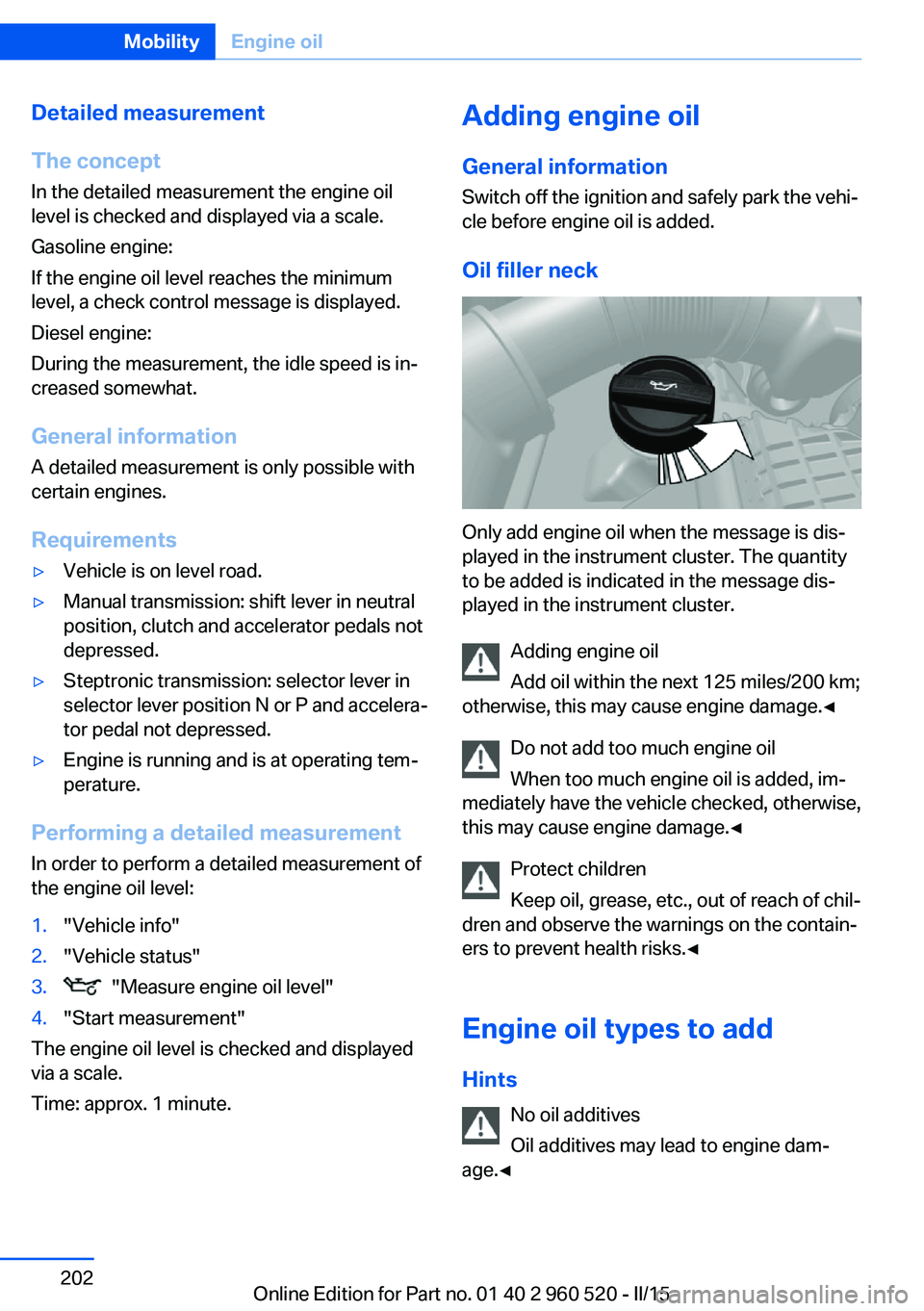
Oil filler neck
Only add engine oil when the message is dis‐
played in the instrument cluster. The quantity
to be added is indicated in the message dis‐
played in the instrument cluster.
Adding engine oil
Add oil within the next 125 miles/200 km;
otherwise, this may cause engine damage.◀
Do not add too much engine oil
When too much engine oil is added, im‐
mediately have the vehicle checked, otherwise,
this may cause engine damage.◀
Protect children
Keep oil, grease, etc., out of reach of chil‐
dren and observe the warnings on the contain‐
ers to prevent health risks.◀
Engine oil types to add Hints No oil additives
Oil additives may lead to engine dam‐
age.◀
Seite 202MobilityEngine oil202
Online Edition for Part no. 01 40 2 960 520 - II/15
Page 208 of 247
CoolantVehicle features and optionsThis chapter describes all standard, country-
specific and optional features offered with the
series. It also describes features that are not
necessarily available in your car, e. g., due to
the selected options or country versions. This
also applies to safety-related functions and
systems. The respectively applicable country
provisions must be observed when using the
respective features and systems.
Hints Danger of burns from hot engine
Do not open the cooling system while
the engine is hot; otherwise, esliding coolant
may cause burns.◀
Suitable additives
Only use suitable additives; otherwise,
engine damage may occur. The additives are
harmful to your health.◀
Coolant consists of water and additives.
Not all commercially available additives are
suitable for the vehicle. Information about the
suitable additives are available from the service
center.
Coolant level
General information
Depending on the engine installation, the cool‐
ant reservoir is located on the right side or the
left side of the engine compartment.
Checking1.Let the engine cool.2.The coolant level is correct if it lies be‐
tween the minimum and maximum marks.The marks are on the side of the coolant
reservoir.SymbolMeaningMaximumMinimum
Adding
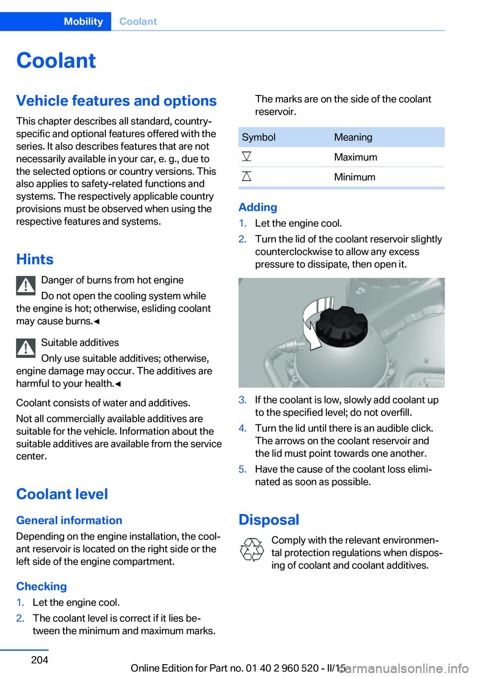
1.Let the engine cool.2.Turn the lid of the coolant reservoir slightly
counterclockwise to allow any excess
pressure to dissipate, then open it.3.If the coolant is low, slowly add coolant up
to the specified level; do not overfill.4.Turn the lid until there is an audible click.
The arrows on the coolant reservoir and
the lid must point towards one another.5.Have the cause of the coolant loss elimi‐
nated as soon as possible.
Disposal
Comply with the relevant environmen‐
tal protection regulations when dispos‐
ing of coolant and coolant additives.
Seite 204MobilityCoolant204
Online Edition for Part no. 01 40 2 960 520 - II/15
Page 209 of 247
MaintenanceVehicle features and options
This chapter describes all standard, country-
specific and optional features offered with the
series. It also describes features that are not
necessarily available in your car, e. g., due to
the selected options or country versions. This
also applies to safety-related functions and
systems. The respectively applicable country
provisions must be observed when using the
respective features and systems.
BMW maintenance system The maintenance system indicates required
maintenance measures, and thereby provides
support in maintaining road safety and the op‐
erational reliability of the vehicle.
In some cases scopes and intervals may vary
according to the country-specific version. Re‐
placement work, spare parts, fuels and lubri‐
cants and wear materials are calculated sepa‐
rately. Additional information is available from
the service center.
Condition Based Service
CBS
Sensors and special algorithms take into ac‐
count the driving conditions of your vehicle.
Based on this, Condition Based Service recog‐
nizes the maintenance requirements.
The system makes it possible to adapt the
amount of maintenance corresponding to your
user profile.
Detailed information on service requirements,
refer to page 82, can be displayed on the Con‐
trol Display.Service data in the remote control
Information on the required maintenance is
continuously stored in the remote control. Your service center will read out this data and
suggest the right array of service procedures for your vehicle.
Therefore, hand your service specialist the re‐
mote control with which the vehicle was driven
most recently.
Storage periods Storage periods during which the vehicle bat‐
tery was disconnected are not taken into ac‐
count.
If this occurs, have a service center update the
time-dependent maintenance procedures,
such as checking brake fluid and, if needed,
changing the engine oil and the microfilter/
activated-charcoal filter.
Service and Warranty
Information Booklet for US
models and Warranty and
Service Guide Booklet for
Canadian models
Please consult your Service and Warranty In‐
formation Booklet for US models and Warranty
and Service Guide Booklet for Canadian mod‐
els for additional information on service re‐
quirements.
Maintenance and repair should be performed
by your service center. Make sure to have reg‐
ular maintenance procedures recorded in the
vehicle's Service and Warranty Information
Booklet for US models, and in the Warranty
and Service Guide Booklet for Canadian mod‐
els. These entries are proof of regular mainte‐
nance.Seite 205MaintenanceMobility205
Online Edition for Part no. 01 40 2 960 520 - II/15
Page 210 of 247
Socket for OBD Onboard
Diagnosis
Note Socket for Onboard Diagnosis
The socket for onboard diagnostics may
only be used by the service center or a work‐
shop that operates in accordance with the
specifications of the vehicle manufacturer with
correspondingly trained personnel and other
authorized persons. Otherwise, use may result
in operating problems for the vehicle.◀
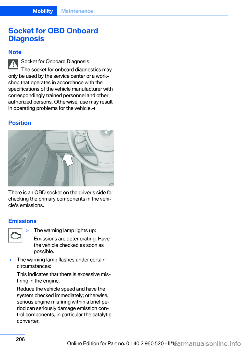
Position
There is an OBD socket on the driver's side for
checking the primary components in the vehi‐
cle's emissions.
Emissions
▷The warning lamp lights up:
Emissions are deteriorating. Have
the vehicle checked as soon as
possible.▷The warning lamp flashes under certain
circumstances:
This indicates that there is excessive mis‐
firing in the engine.
Reduce the vehicle speed and have the
system checked immediately; otherwise,
serious engine misfiring within a brief pe‐
riod can seriously damage emission con‐
trol components, in particular the catalytic
converter.Seite 206MobilityMaintenance206
Online Edition for Part no. 01 40 2 960 520 - II/15
Page 212 of 247
You can obtain a selection of replacement
bulbs at the service center.
Danger of burns
Only change bulbs when they are cool;
otherwise, there is a danger of getting
burned.◀
Working on the lighting system
When working on the lighting system,
you should always reel off the lights affected to
prevent short circuits.
To avoid possible injury or equipment damage
when replacing bulbs, observe any instructions
provided by the bulb manufacturer.◀
Do not perform work/bulb replacement
on xenon headlights
Have any work on the xenon lighting system,
including bulb replacement, performed only by
a service center. Due to the high voltage
present in the system, there is a danger of fatal
injuries if work is carried out improperly.◀
Do not touch the bulbs
Do not touch the glass of new bulbs with
your bare hands, as even minute amounts of
contamination will burn into the bulb's surface
and reduce its service life.
Use a clean tissue, cloth or something similar,
or hold the bulb by its base.◀
Light-emitting diodes (LEDs)
Some items of equipment use light-emitting
diodes installed behind a cover as a light
source.
These light-emitting diodes, which are related
to conventional lasers, are officially designated as Class 1 light-emitting diodes.
Do not remove the covers
Do not remove the covers, and never
stare into the unfiltered light for several hours;
otherwise, irritation of the retina could result.◀Headlight glass
Condensation can form on the inside of the ex‐
ternal lights in cool or humid weather. When
driving with the light switched on, the conden‐
sation evaporates after a short time. The head‐
light glass does not need to be changed.
If the headlights do not dim despite driving
with the light switched on, increasing humidity
forms, e. g. water droplets in the light, have the service center check this.
Headlight setting The headlight adjustments can be affected by
changing lights and bulbs. Have the head‐
lights' settings checked and corrected by serv‐
ice after a replacement.
Front lights, bulb replacement
Xenon headlights
Xenon headlights
Because of the long life of these bulbs, the
likelihood of failure is very low. Switching the
lights on and off frequently shortens their life.
If a bulb fails, reel on the front fog lights and
continue the trip with great care. Comply with local regulations.
Do not perform work/bulb replacement
on xenon headlights
Have any work on the xenon lighting system,
including bulb replacement, performed only by
a service center. Due to the high voltage present in the system, there is a danger of fatal
injuries if work is carried out improperly.◀
For checking and adjusting headlamp aim,
please contact your BMW center.Seite 208MobilityReplacing components208
Online Edition for Part no. 01 40 2 960 520 - II/15
Page 218 of 247

The added amount of acid is sufficient for the
service life of the battery.
Further information about the battery can be
obtained from your service center.
Battery replacement Use approved vehicle batteries only
Only use vehicle batteries that have been
approved for your vehicle by the manufacturer;
otherwise, the vehicle could be damaged and
systems or functions may not be fully availa‐
ble.◀
After a battery replacement, have the battery
registered on the vehicle by the service center
to ensure that all comfort features are fully
available and that any Check Control mes‐
sages of these comfort features are no longer
displayed.
Charging the battery
General information
Make sure that the battery is always suffi‐
ciently charged to guarantee that the battery
remains usable for its full service life.
The battery may need to be charged in the fol‐
lowing cases:▷When making frequent short-distance
drives.▷If the vehicle is not used for prolonged pe‐
riods, longer than a month.
Hints
Do not connect charging devices to the
12 volt socket in the vehicle
Do not connect battery chargers to the fac‐
tory-installed 12 volt sockets in the vehicle as
this may damage the vehicle battery due to an
increased power consumption.◀
Starting aid terminals
In the vehicle, only charge the battery via the
starting aid terminals, refer to page 218, in the
engine compartment with the engine off.
Power failure After a temporary power loss, some equipment
needs to be newly initialized or individual set‐
tings updated, e. g.:▷Seat and mirror memory: store the posi‐
tions again.▷Time: update.▷Date: update.▷Glass sunroof and sliding visor: initialize
the system, refer to page 48.
Disposing of old batteries
Have old batteries disposed of by your
service center or bring them to a recy‐
cling center.
Maintain the battery in an upright position for
transport and storage. Secure the battery so
that it does not tip over during transport.
Fuses Hints Replacing fuses
Never attempt to repair a blown fuse and
do not replace a defective fuse with a substi‐
tute of another color or amperage rating; this
could lead to a circuit overload, ultimately re‐
sulting in a fire in the vehicle.◀
Plastic tweezers and information on the fuse
types and locations are stored in the fuse box
in the trunk.
Seite 214MobilityReplacing components214
Online Edition for Part no. 01 40 2 960 520 - II/15
Page 221 of 247
When the emergency request is received
at the BMW Response Center, the BMW
Response Center contacts you and takes
further steps to help you.
Even if you are unable to respond, the
BMW Response Center can take further
steps to help you under certain circum‐
stances.
For this, data are transmitted to the BMW
Response Center which serve to deter‐
mine the necessary rescue measures. E. g.
the current position of the vehicle, if it can
be established.▷If the LED is flashing green, but the BMW
Response Center can no longer be heard
via the speaker, you can nevertheless still
be heard at the BMW Response Center.
Initiating an Emergency Request
automatically
Under certain conditions, an Emergency Re‐
quest is automatically initiated immediately af‐
ter a severe accident. Automatic Collision Noti‐
fication is not affected by pressing the SOS
button.
Warning triangle
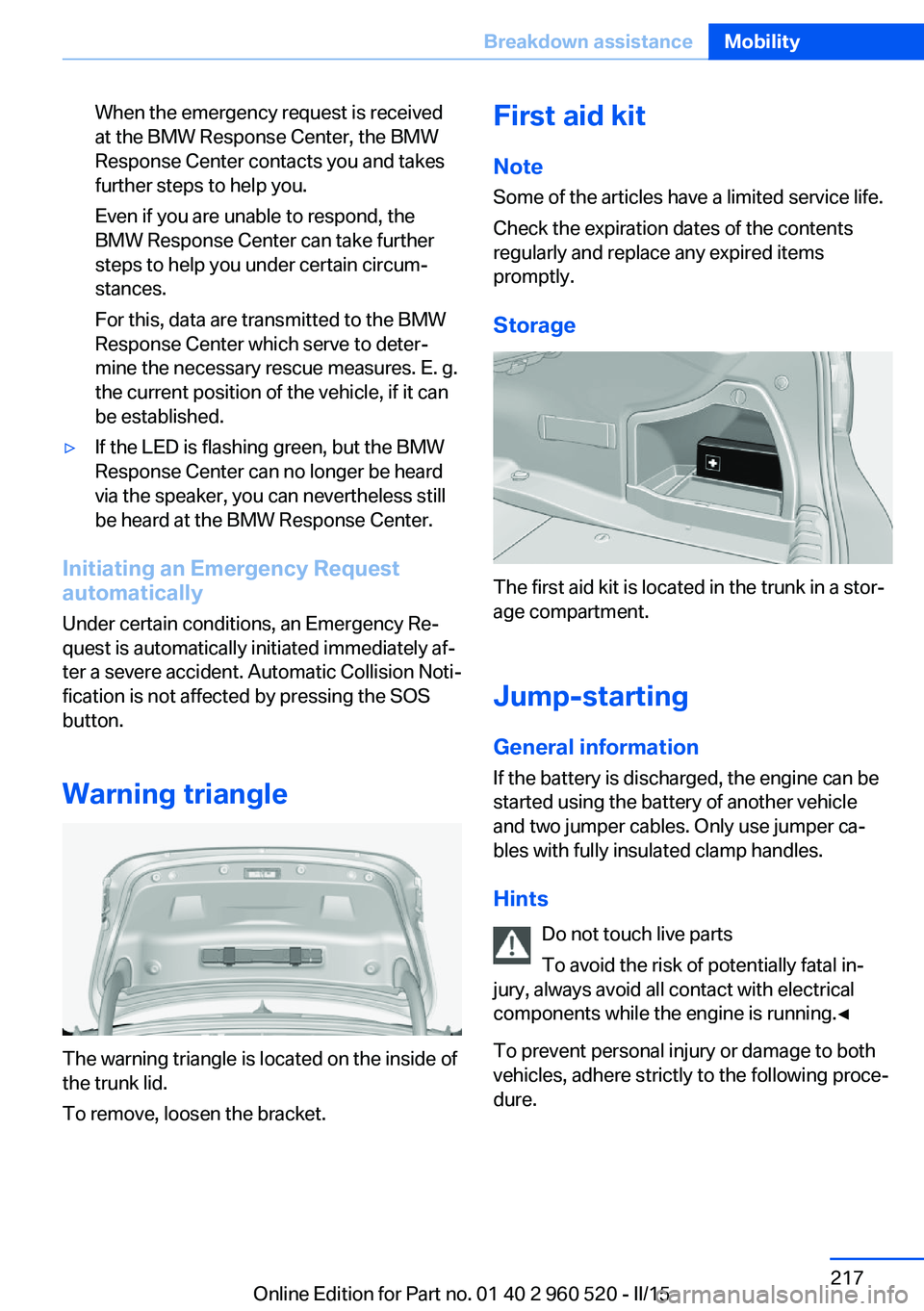
The warning triangle is located on the inside of
the trunk lid.
To remove, loosen the bracket.
First aid kit
Note
Some of the articles have a limited service life.
Check the expiration dates of the contents
regularly and replace any expired items
promptly.
Storage
The first aid kit is located in the trunk in a stor‐
age compartment.
Jump-starting General information
If the battery is discharged, the engine can be
started using the battery of another vehicle
and two jumper cables. Only use jumper ca‐
bles with fully insulated clamp handles.
Hints Do not touch live parts
To avoid the risk of potentially fatal in‐
jury, always avoid all contact with electrical
components while the engine is running.◀
To prevent personal injury or damage to both
vehicles, adhere strictly to the following proce‐
dure.
Seite 217Breakdown assistanceMobility217
Online Edition for Part no. 01 40 2 960 520 - II/15
Page 222 of 247
PreparationBodywork contact between vehicles
Make sure that there is no contact be‐
tween the bodywork of the two vehicles; other‐
wise, there is a danger of short circuits.◀1.Check whether the battery of the other ve‐
hicle has a voltage of 12 volts. This infor‐
mation can be found on the battery.2.Switch off the engine of the assisting vehi‐
cle.3.Switch off any electronic systems/power
consumers in both vehicles.
Starting aid terminals
Connecting order
Connect the jumper cables in the correct
order to prevent risk of injury from arcing.◀
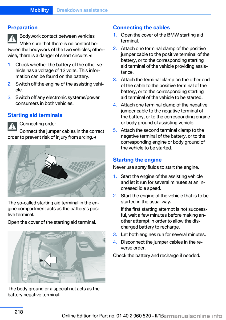
The so-called starting aid terminal in the en‐
gine compartment acts as the battery's posi‐
tive terminal.
Open the cover of the starting aid terminal.
The body ground or a special nut acts as the
battery negative terminal.
Connecting the cables1.Open the cover of the BMW starting aid
terminal.2.Attach one terminal clamp of the positive
jumper cable to the positive terminal of the
battery, or to the corresponding starting
aid terminal of the vehicle providing assis‐
tance.3.Attach the terminal clamp on the other end
of the cable to the positive terminal of the
battery, or to the corresponding starting
aid terminal of the vehicle to be started.4.Attach one terminal clamp of the negative
jumper cable to the negative terminal of
the battery, or to the corresponding engine
or body ground of assisting vehicle.5.Attach the second terminal clamp to the
negative terminal of the battery, or to the
corresponding engine or body ground of
the vehicle to be started.
Starting the engine
Never use spray fluids to start the engine.
1.Start the engine of the assisting vehicle
and let it run for several minutes at an in‐
creased idle speed.2.Start the engine of the vehicle that is to be
started in the usual way.
If the first starting attempt is not success‐
ful, wait a few minutes before making an‐
other attempt in order to allow the dis‐
charged battery to recharge.3.Let both engines run for several minutes.4.Disconnect the jumper cables in the re‐
verse order.
Check the battery and recharge if needed.
Seite 218MobilityBreakdown assistance218
Online Edition for Part no. 01 40 2 960 520 - II/15