2016 BMW 4 SERIES GRAN COUPE front bumper
[x] Cancel search: front bumperPage 115 of 249

The system sounds a warning before an immi‐
nent collision and actuates brakes independ‐
ently if needed.
The automatic braking intervention is executed
with limited braking force and for a brief period
only.
If the vehicle is equipped with Active Cruise
Control with Stop & Go, the front-end collision
warning is controlled via the cruise control ra‐
dar sensor.
The front-end collision warning is available
even if cruise control has been deactivated.
With the vehicle approaching another vehicle
intentionally the collision warning is delayed
avoiding false alarm.
General information
The system issues a two-phase warning of a
possible danger of collision with vehicles at
speeds above approx. 3 mph/5 km/h. Time of
warnings may vary with the current driving sit‐
uation.
Detection range
It responds to objects if they are detected by
the system.
Hints Personal responsibility
The system does not serve as a substi‐
tute for the driver's personal judgment of the
traffic situation.
Be aware of the traffic situation and the vehi‐
cle's surroundings at all times, otherwise acci‐
dents are still possible despite all warnings.◀
Adapting your speed and driving styleThe displays and warnings of the system
do not relieve the driver of the responsibility to
adapt his or her driving speed and style to the
traffic conditions.◀
Be alert
Due to system limitations, warnings may
be not issued at all, or may be issued late or
improperly. Therefore, always be alert and
ready to intervene; otherwise, there is the risk
of an accident.◀
Tow-starting and towing
For tow-starting or towing, switch off the
Intelligent Safety systems; otherwise malfunc‐
tions of the individual braking systems might
lead to accidents.◀
At a glance
Button in the vehicle
Intelligent Safety button
Radar sensor
A radar sensor is located in the front bumper
for detecting vehicles on the road ahead of the
vehicle.
Seite 111SafetyControls111
Online Edition for Part no. 01 40 2 960 707 - II/15
Page 121 of 249

▷When using the turn signal.
System limits
The system may not be fully functional in the
following situations:
▷In heavy fog, rain or snowfall.▷In the event of missing, worn, poorly visi‐
ble, merging, diverging, or multiple lane
markings such as in construction areas.▷When lane markings are covered in snow,
ice, dirt or water.▷In tight curves or on narrow lanes.▷When the lane markings are covered by
objects.▷When driving very close to the vehicle in
front of you.▷When driving toward bright lights.▷When the windshield in front of the interior
rearview mirror is fogged over, dirty or cov‐
ered with stickers, etc.▷During calibration of the camera immedi‐
ately after vehicle shipment.
Active Blind Spot Detection
The concept
Two radar sensors below the rear bumper
monitor the area behind and next to the vehicle
at speeds above approx. 30 mph/50 km/h.
The system indicates whether there are vehi‐
cles in the blind spot, arrow 1, or approaching
from behind on the adjacent lane, arrow 2.
The lamp in the exterior mirror housing is dim‐
med.
Before you change lanes after setting the turn
signal, the system issues a warning in the sit‐
uations described above.
The lamp in the exterior mirror housing flashes
and the steering wheel vibrates.
Hints Personal responsibility
The system does not serve as a substi‐
tute for the driver's personal judgment of the
traffic situation.
Be aware of the traffic situation and the vehi‐
cle's surroundings at all times, otherwise acci‐
dents are still possible despite all warnings.◀
At a glance
Button in the vehicle
Active Blind Spot Detection
Seite 117SafetyControls117
Online Edition for Part no. 01 40 2 960 707 - II/15
Page 130 of 249

Before leaving the vehicle, secure it
against moving on its own.
Before leaving the vehicle with the engine run‐
ning: set the parking brake and ensure that the
Steptronic transmission is in position P. Other‐
wise, the vehicle may begin to move.◀
Overview
Buttons on the steering wheelPress but‐
tonFunctionSystem on/off, interrupt, refer
to page 126Store, maintain speed, refer to
page 127Resume speed, refer to
page 128Reduce distance, refer to
page 128Increase distance, refer to
page 128rocker switch:
Maintain, store, change speed,
refer to page 127
Buttons are arranged according to vehicle's
series, optional features and country specifica‐
tions.
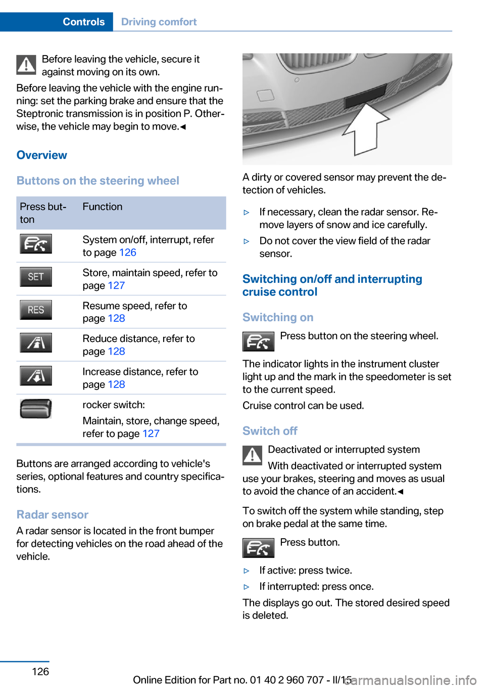
Radar sensor
A radar sensor is located in the front bumper for detecting vehicles on the road ahead of the
vehicle.
A dirty or covered sensor may prevent the de‐
tection of vehicles.
▷If necessary, clean the radar sensor. Re‐
move layers of snow and ice carefully.▷Do not cover the view field of the radar
sensor.
Switching on/off and interrupting cruise control
Switching on Press button on the steering wheel.
The indicator lights in the instrument cluster
light up and the mark in the speedometer is set
to the current speed.
Cruise control can be used.
Switch off Deactivated or interrupted system
With deactivated or interrupted system
use your brakes, steering and moves as usual
to avoid the chance of an accident.◀
To switch off the system while standing, step
on brake pedal at the same time.
Press button.
▷If active: press twice.▷If interrupted: press once.
The displays go out. The stored desired speed
is deleted.
Seite 126ControlsDriving comfort126
Online Edition for Part no. 01 40 2 960 707 - II/15
Page 137 of 249

When cruise control is maintained or stored,
DSC Dynamic Stability Control will be turned
on if needed.
Changing the speed
Press the rocker switch up or down repeatedly
until the desired speed is set.
If active, the displayed speed is stored and the
vehicle reaches the stored speed when the
road is clear.▷Each time the rocker switch is pressed to
the point of resistance, the desired speed
increases or decreases by approx.
1 mph/1 km/h.▷Each time the rocker switch is pressed
past the point of resistance, the desired
speed increases or decreases by a maxi‐
mum of 5 mph/10 km/h.
The maximum speed that can be set de‐
pends on the vehicle.▷Pressing the rocker switch to the resist‐
ance point and holding it accelerates or de‐
celerates the vehicle without requiring
pressure on the accelerator pedal.
After the rocker switch is released, the ve‐
hicle maintains its final speed. Pressing the
switch beyond the resistance point causes
the vehicle to accelerate more rapidly.
Resuming the desired speed
Press button.
The stored speed is reached and maintained. Displays in the instrument cluster
Indicator lamp Depending on how the vehicle is equip‐
ped, the indicator lamp in the instru‐
ment cluster indicates whether the sys‐
tem is switched on.
Desired speed▷The marking lights up green:
the system is active.▷The marking lights up or‐
ange: the system has been
interrupted.▷The marking does not light up: the system
is switched off.
Brief status display
Selected desired speed.
If --- appears briefly on the display for Check
Control messages, it is possible that the sys‐
tem requirements are currently not ready for
operations.
Displays in the Head-up Display Some system information can also be dis‐played in the Head-up Display.
PDC Park Distance Control
The concept PDC is a support when parking. When you
slowly approach an object in the rear - or also
in the front of the vehicle if the feature is availa‐
ble - then the object is reported through:
▷Signal tones.▷Visual display.
General information
Ultrasound sensors in the bumpers measure
the distances from objects.
The maneuvering range, depending on the ob‐
stacle and environmental conditions, is approx.
6 ft/2 m.
An acoustic warning is first given:
▷By the front sensors and the two rear cor‐
ner sensors at approx. 24 in/60 cm.Seite 133Driving comfortControls133
Online Edition for Part no. 01 40 2 960 707 - II/15
Page 143 of 249

At a glance
Button in the vehicle
Side View
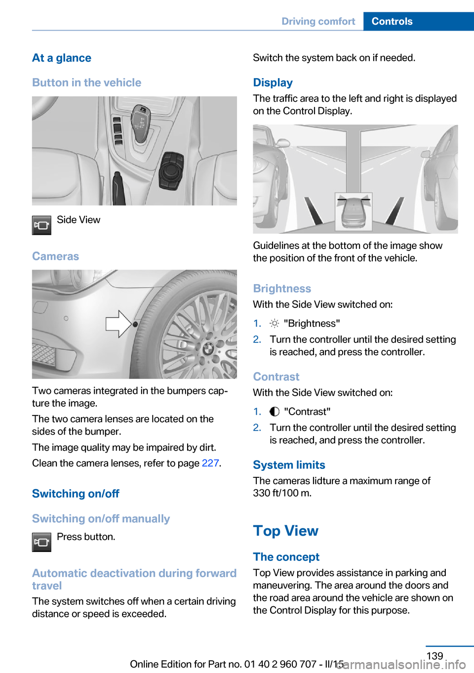
Cameras
Two cameras integrated in the bumpers cap‐
ture the image.
The two camera lenses are located on the
sides of the bumper.
The image quality may be impaired by dirt.
Clean the camera lenses, refer to page 227.
Switching on/off
Switching on/off manually Press button.
Automatic deactivation during forward travel
The system switches off when a certain driving
distance or speed is exceeded.
Switch the system back on if needed.
Display
The traffic area to the left and right is displayed
on the Control Display.
Guidelines at the bottom of the image show
the position of the front of the vehicle.
Brightness With the Side View switched on:
1. "Brightness"2.Turn the controller until the desired setting
is reached, and press the controller.
Contrast
With the Side View switched on:
1. "Contrast"2.Turn the controller until the desired setting
is reached, and press the controller.
System limits
The cameras lidture a maximum range of
330 ft/100 m.
Top View
The concept Top View provides assistance in parking and
maneuvering. The area around the doors and
the road area around the vehicle are shown on
the Control Display for this purpose.
Seite 139Driving comfortControls139
Online Edition for Part no. 01 40 2 960 707 - II/15