2016 BMW 328D XDRIVE SEDAN check
[x] Cancel search: checkPage 85 of 257

Supplementary text messages
Additional information, such as on the cause of
an error or the required action, can be called up
via Check Control.
With urgent messages the added text will be
automatically displayed on the Control Display.
Symbols
Depending on the Check Control message, the
following functions can be selected.▷ "Owner's Manual"
Display additional information about the
Check Control message in the Integrated
Owner's Manual.▷ "Service request"
Contact your service center.▷ "Roadside Assistance"
Contact Roadside Assistance.
Hiding Check Control messages
Press the onboard computer button on the
turn signal lever.
▷Some Check Control messages are dis‐
played continuously and are not cleared
until the malfunction is eliminated. If sev‐
eral malfunctions occur at once, the mes‐
sages are displayed consecutively.
These messages can be faded for approx.
8 seconds. After this time, they are dis‐
played again automatically.▷Other Check Control messages are faded
automatically after approx. 20 seconds.They are stored and can be displayed
again later.
Displaying stored Check Control
messages
On the Control Display:
1."Vehicle info"2."Vehicle status"3. "Check Control"4.Select the text message.
Messages after trip completion Special messages displayed while driving are
displayed again after the ignition is switched
off.
Fuel gauge Vehicle tilt position may cause
the display to vary.
Depending on the equipment
version, the arrow beside the
fuel pump symbol shows which
side of the vehicle the fuel filler flap is on.
Hints on refueling, refer to page 182.
Tachometer Always avoid engine speeds in the red warning
field. In this range, the fuel supply is inter‐
rupted to protect the engine.
Engine oil temperature
▷Cold engine: the pointer is at
the low temperature end.
Drive at moderate engine
and vehicle speeds.▷Normal operating tempera‐
ture: the pointer is in theSeite 81DisplaysControls81
Online Edition for Part no. 01 40 2 960 440 - II/15
Page 86 of 257

middle or in the left half of
the temperature display.▷Hot engine: the pointer is at the high end of
the temperature range. A Check Control
message is also displayed.
Coolant temperature
If the coolant along with the engine becomes
too hot, a Check Control message is displayed.
Check the coolant level, refer to page 209.
Odometer and trip odometer Display
▷Odometer, arrow 1.▷Trip odometer, arrow 2.
Show/reset kilometers Press the knob.
▷When the ignition is
switched off, the time, the
external temperature and
the odometer are displayed.▷When the ignition is switched on, the trip
odometer is reset.
External temperature
If the indicator drops to
+37 ℉/+3 ℃ or lower, a signal
sounds.
A Check Control message is displayed.
There is an increased risk of ice on roads.
Ice on roads
Even at temperatures above
+37 ℉/+3 ℃, roads might be icy.
Therefore, drive carefully on bridges and
shaded roads, e.g., to avoid the increased risk
of an accident.◀
Time The time is displayed at the bot‐
tom of the instrument cluster.
Setting the time and time for‐
mat, refer to page 89.
Date The date is displayed in the
computer.
Setting the date and date for‐
mat, refer to page 89.
Range
Display With a low remaining range:▷A Check Control message is
displayed briefly.▷The remaining range is
shown on the on-board co‐
mupter.▷With a dynamic driving style - e.g., taking
curves aggressively - engine operation
might vary.
The Check Control message appears continu‐
ously below a range of approx. 30 miles/50 km.
Refuel promptly
Refuel no later than at a range of
30 miles/50 km or engine operation might fail
and damage might occur.◀
Seite 82ControlsDisplays82
Online Edition for Part no. 01 40 2 960 440 - II/15
Page 87 of 257
Displaying the cruising rangeDepending on your vehicle's optional features,
the range can also be displayed as bar in the
instrument cluster.1."Settings"2."Instrument cluster"3."Additional indicators"
Current fuel consumption
Instrument cluster Displays the current fuel con‐
sumption. Check whether you
are currently driving in an effi‐
cient and environmentally-
friendly manner.
Instrum. cluster with enhanced
features
Displays the current fuel con‐
sumption. Check whether you
are currently driving in an effi‐
cient and environmentally-
friendly manner.
Displaying the current fuel
consumption
1."Settings"2."Instrument cluster"3."Additional indicators"
The bar display for the current fuel consump‐
tion is displayed in the instrument cluster.
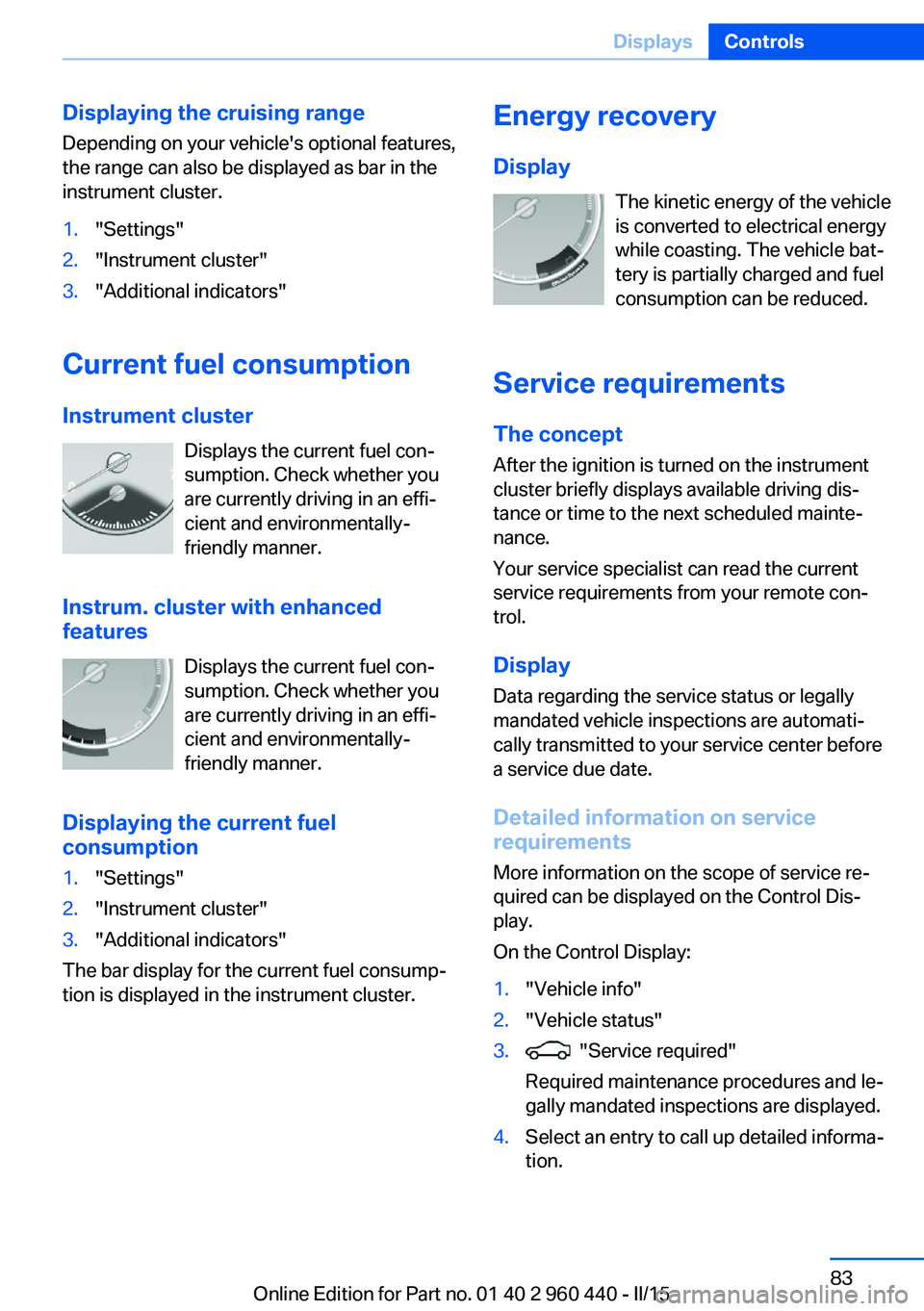
Energy recovery
Display The kinetic energy of the vehicle
is converted to electrical energy while coasting. The vehicle bat‐
tery is partially charged and fuel
consumption can be reduced.
Service requirements The concept
After the ignition is turned on the instrument
cluster briefly displays available driving dis‐
tance or time to the next scheduled mainte‐
nance.
Your service specialist can read the current
service requirements from your remote con‐
trol.
Display
Data regarding the service status or legally
mandated vehicle inspections are automati‐
cally transmitted to your service center before
a service due date.
Detailed information on service
requirements
More information on the scope of service re‐
quired can be displayed on the Control Dis‐
play.
On the Control Display:1."Vehicle info"2."Vehicle status"3. "Service required"
Required maintenance procedures and le‐
gally mandated inspections are displayed.4.Select an entry to call up detailed informa‐
tion.Seite 83DisplaysControls83
Online Edition for Part no. 01 40 2 960 440 - II/15
Page 88 of 257

SymbolsSym‐
bolsDescriptionNo service is currently required.The deadline for scheduled mainte‐
nance or a legally mandated inspec‐
tion is approaching.The service deadline has already
passed.
Entering appointment dates
Enter the dates for the required inspections.
Make sure that the vehicle's date and time are
set correctly.
On the Control Display:
1."Vehicle info"2."Vehicle status"3. "Service required"4."§ Vehicle inspection"5."Date:"6.Adjust the settings.7.Confirm.
The entered date is stored.
Automatic Service Request
Data regarding the service status or legally
mandated vehicle inspections are automati‐
cally transmitted to your service center before
a service due date.
You can check when your service center was
notified.
On the Control Display:
1."Vehicle info"2."Vehicle status"3.Open "Options".4."Last Service Request"Gear shift indicator
The conceptThe system recommends the most fuel effi‐
cient gear for the current driving situation.
Depending on the vehicle's features and coun‐
try version of the vehicle, the gear shift indica‐
tor is active in the manual mode of the Step‐
tronic transmission and with manual
transmission.
Suggestions to shift gear up or down are dis‐
played in the instrument cluster.
Manual transmission: displayingSymbolDescriptionFuel efficient gear is set.Shift up to fuel efficient gear.Shift down to fuel efficient gear.Shift into neutral.
Steptronic transmission: displays
ExampleDescriptionFuel efficient gear is set.Shift into fuel efficient gear.Seite 84ControlsDisplays84
Online Edition for Part no. 01 40 2 960 440 - II/15
Page 95 of 257

If the image is distorted, check the basic set‐
tings.
Switching on/off1."Settings"2."Head-Up Display"3."Head-Up Display"
Display
Overview
▷Speed.▷Navigation system.▷Check Control messages.▷Selection list from the instrument cluster.▷Driver assistance systems.
Some of this information is only displayed
briefly as needed.
Selecting displays in the Head-up
Display
On the Control Display:
1."Settings"2."Head-Up Display"3."Displayed information"4.Select the desired displays in the Head-up
Display.
Settings are stored for the profile currently in
use.
Setting the brightness
The brightness is automatically adjusted to the
ambient brightness.
The basic setting can be adjusted manually.
On the Control Display:
1."Settings"2."Head-Up Display"3."Brightness"4.Turn the controller.When the low beams are activated, the bright‐
ness of the Head-up Display can be addition‐
ally influenced using the instrument lighting.
Settings are stored for the profile currently in
use.
Adjusting the height
On the Control Display:1."Settings"2."Head-Up Display"3."Height"4.Turn the controller.
Settings are stored for the profile currently in
use.
Setting the rotation
On the Control Display:
1."Settings"2."Head-Up Display"3."Rotation"4.Turn the controller.
Settings are stored for the profile currently in
use.
Special windshield
The windshield is part of the system.
The shape of the windshield makes it possible
to display a precise image.
A film in the windshield prevents double im‐
ages from being displayed.
Therefore, have the special windshield re‐
placed by a service center only.
Seite 91DisplaysControls91
Online Edition for Part no. 01 40 2 960 440 - II/15
Page 98 of 257

In tight curves, e.g., on mountainous roads or
when turning, one of the two front fog lights is
switched on as a turning lamp. As a result the
inside of the curve is better lighted.
ActivatingPosition of switch
with the ignition
switched on.
To avoid blinding oncoming traffic, the Adap‐
tive Light Control does not swivel to the driv‐
er's side when the vehicle is at a standstill.
The turning lights are automatically switched
on depending on the steering angle or the use
of turn signals.
When driving in reverse, the turning lights may
be automatically switched on regardless of the
steering angle.
Malfunction A Check Control message is displayed.
Adaptive Light Control is malfunctioning or has
failed. Have the system checked as soon as
possible.
High-beam Assistant
The concept When the low beams are activated, this system
automatically switches the high beams on and
off or suppresses the light in the areas that
blind oncoming traffic. The procedure is con‐
trolled by a camera on the front of the interior
rearview mirror. The assistant ensures that the
high beams are activated whenever the traffic
situation allows. The driver can intervene at
any time and switch the high beams non and
off as usual.
Note Personal responsibility
The High-beam Assistant cannot serve
as a substitute for the driver's personal judg‐
ment of when to use the high beams. There‐
fore, manually reel off the high beams in situa‐
tions where required to avoid a safety risk.◀
Activating1.Depending on the equipment, turn the light
switch into position
or .
2.Press button on the turn signal lever, ar‐
row.
The indicator lamp in the instrument
cluster lights up.
When the low beams are on, the lights are au‐
tomatically brightened or dimmed.
The system responds to light from oncoming
traffic and traffic driving ahead of you, and to
adequate illumination, e.g., in towns and cities.
The blue indicator lamp in the instru‐
ment cluster lights up when the system
switches on the high beams. Depend‐
ing on the version of the system in the vehicle, the high beams may not switch off for oncom‐
ing vehicles, but may only be dimmed in the
areas that blind oncoming traffic. In this case,
the blue indicator light will stay on.
Seite 94ControlsLights94
Online Edition for Part no. 01 40 2 960 440 - II/15
Page 102 of 257

Ejection MitigationThe head airbag system is designed as an
ejection mitigation countermeasure to reduce
the likelihood of ejections of vehicle occupants
through side windows during rollovers or side
impact events.
Knee airbag The knee airbag supports the legs in a frontal
impact.
Protective action
Airbags are not triggered in every impact situa‐
tion, e.g., in less severe accidents or rear-end
collisions.
Information on how to ensure the optimal
protective effect of the airbags▷Keep at a distance from the airbags.▷Always grasp the steering wheel on the
steering wheel rim, holding your hands at
the 3 o'clock and 9 o'clock positions, to
keep the risk of injury to your hands or
arms as low as possible when the airbag is
triggered.▷There should be no person, animals, or ob‐
jects between an airbag and a person.▷Do not use the cover of the front airbag on
the front passenger side as a storage area.▷Dashboard and windshield on the front
passenger side must stay clear - do not at‐
tach adhesive labels or coverings and do
not attach brackets or cables, e. g., for GPS
devices or' mobile phones.▷Make sure that the front passenger is sit‐
ting correctly, i.e., keeps his or her feet and
legs in the footwell; otherwise, leg injuries
might occur when front airbag is activated.▷Do not place slip covers, seat cushions or
other objects on the front passenger seat
that are not approved specifically for seats
with integrated side airbags.▷Do not hang pieces of clothing, such as
jackets, over the backrests.▷Make sure that occupants keep their heads
away from the side airbag and do not rest
against the head airbag; otherwise, injuries
might occur when airbag is activated.▷Do not remove the airbag system.▷Do not remove the steering wheel.▷Do not apply adhesive materials to the air‐
bag cover panels, do not cover them or
modify them in any way.▷Never modify either the individual compo‐
nents or the wiring in the airbag system.
This also applies to steering wheel covers,
the dashboard, the seats, the roof pillars
and the sides of the roofliner.◀
Even when you follow all instructions very
closely, injury from contact with the airbags
cannot be ruled out in certain situations.
The ignition and inflation noise may lead to
short-term and, in most cases, temporary
hearing impairment in sensitive individuals.
Malfunction, deactivation and after de‐
ploying the airbags
Do not touch the individual components imme‐
diately after the system has been triggered;
otherwise, you may risk burns.
Only have the airbags checked, repaired or dis‐
mantled and the airbag generator scrapped by
the service center or an authorized repair shop
for handling explosives.
Non-professional attempts to service the sys‐
tem could lead to failure in an emergency or
unintentional activation of the airbag - both
may lead to injury.◀
Warnings and information on the airbags are also found on the sun visors.
Functional readiness of the airbag
system
When the ignition is reel on, the warn‐
ing lamp in the instrument cluster lights
up briefly and thereby indicates the op‐
Seite 98ControlsSafety98
Online Edition for Part no. 01 40 2 960 440 - II/15
Page 103 of 257

erational readiness of the entire airbag system
and the belt tensioner.
Airbag system malfunctioning▷Warning lamp does not come on when the
ignition is turned on.▷The warning lamp lights up continuously.
In case of a malfunction have airbag sys‐
tem checked immediately.
In case of a malfunction have airbag system
checked immediately; otherwise, there is a risk
that the system does not function as expected
in case of a severe accident.◀
Automatic deactivation of the front-
seat passenger airbags
The system reads if the front passenger seat is
occupied by measuring the human body's re‐
sistance.
Front, knee and side airbag on the front pas‐
senger's side are either activated or deacti‐
vated.
Leave feet in the footwell
Make sure that the front passenger
keeps his or her feet in the footwell; otherwise,
proper functioning of the front passenger air‐
bag might not be assured.◀
Child restraint fixing system in the front
passenger seat
Before transporting a child on the front pas‐
senger seat, refer to the safety notes and in‐
structions for children on the front passenger
seat, see Children.◀
Malfunction of the automatic
deactivation system
When transporting older children and adults,
the front-seat passenger airbags may be deac‐
tivated in certain sitting positions. In this case,
the indicator lamp for the front-seat passenger
airbags lights up.
In this case, change the sitting position so that
the front-seat passenger airbags are activated
and the indicator lamp goes out.
If it is not possible to activate the airbags, have
the person sit in the rear.
To enable correct recognition of the occupied
seat cushion▷Do not attach covers, cushions, ball mats
or other items to the front passenger seat
unless they are specifically recommended
by your vehicle's manufacturer.▷Do not place any electronic devices on the
passenger seat if a child restraint system is
to be installed on it.▷Do not place objects under the seat that
could press against the seat from below.▷No moisture in or on the seat.
Indicator lamp for the front-seat
passenger airbags
The indicator lamp for the front-seat passen‐
ger airbags indicates the operating state of the
front-seat passenger airbags.
The lamp indicates whether the airbags are ei‐
ther activated or deactivated.
▷The indicator lamp lights up
when a child is properly
seated in a child restraint fix‐
ing system or when the seat
is empty. The airbags on the
front passenger side are not
activated.▷The indicator lamp does not light up when,
e.g., a correctly seated person of sufficientSeite 99SafetyControls99
Online Edition for Part no. 01 40 2 960 440 - II/15