2016 BMW 3 SERIES SPORTS WAGON control panel
[x] Cancel search: control panelPage 23 of 255
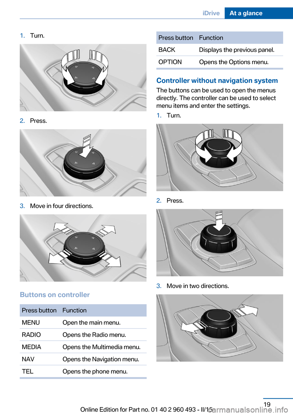
1.Turn.2.Press.3.Move in four directions.
Buttons on controller
Press buttonFunctionMENUOpen the main menu.RADIOOpens the Radio menu.MEDIAOpens the Multimedia menu.NAVOpens the Navigation menu.TELOpens the phone menu.Press buttonFunctionBACKDisplays the previous panel.OPTIONOpens the Options menu.
Controller without navigation system
The buttons can be used to open the menus
directly. The controller can be used to select
menu items and enter the settings.
1.Turn.2.Press.3.Move in two directions.Seite 19iDriveAt a glance19
Online Edition for Part no. 01 40 2 960 493 - II/15
Page 24 of 255
Buttons on controllerPress buttonFunctionMENUOpen the main menu.AudioOpen audio menu last listened
to, switch between audio me‐
nus.TELOpens the phone menu.BACKOpen previous panel.OPTIONOpens the Options menu.
Operating concept
Opening the main menu Press button.
The main menu is displayed.
All iDrive functions can be called up via the
main menu.
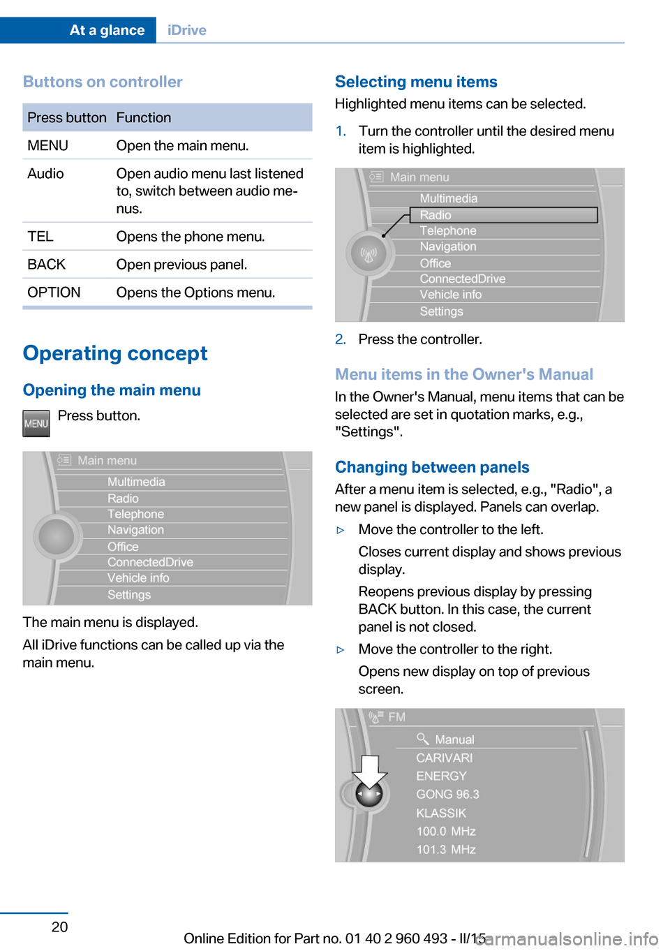
Selecting menu items
Highlighted menu items can be selected.1.Turn the controller until the desired menu
item is highlighted.2.Press the controller.
Menu items in the Owner's Manual
In the Owner's Manual, menu items that can be
selected are set in quotation marks, e.g.,
"Settings".
Changing between panels
After a menu item is selected, e.g., "Radio", a
new panel is displayed. Panels can overlap.
▷Move the controller to the left.
Closes current display and shows previous
display.
Reopens previous display by pressing
BACK button. In this case, the current
panel is not closed.▷Move the controller to the right.
Opens new display on top of previous
screen.Seite 20At a glanceiDrive20
Online Edition for Part no. 01 40 2 960 493 - II/15
Page 25 of 255
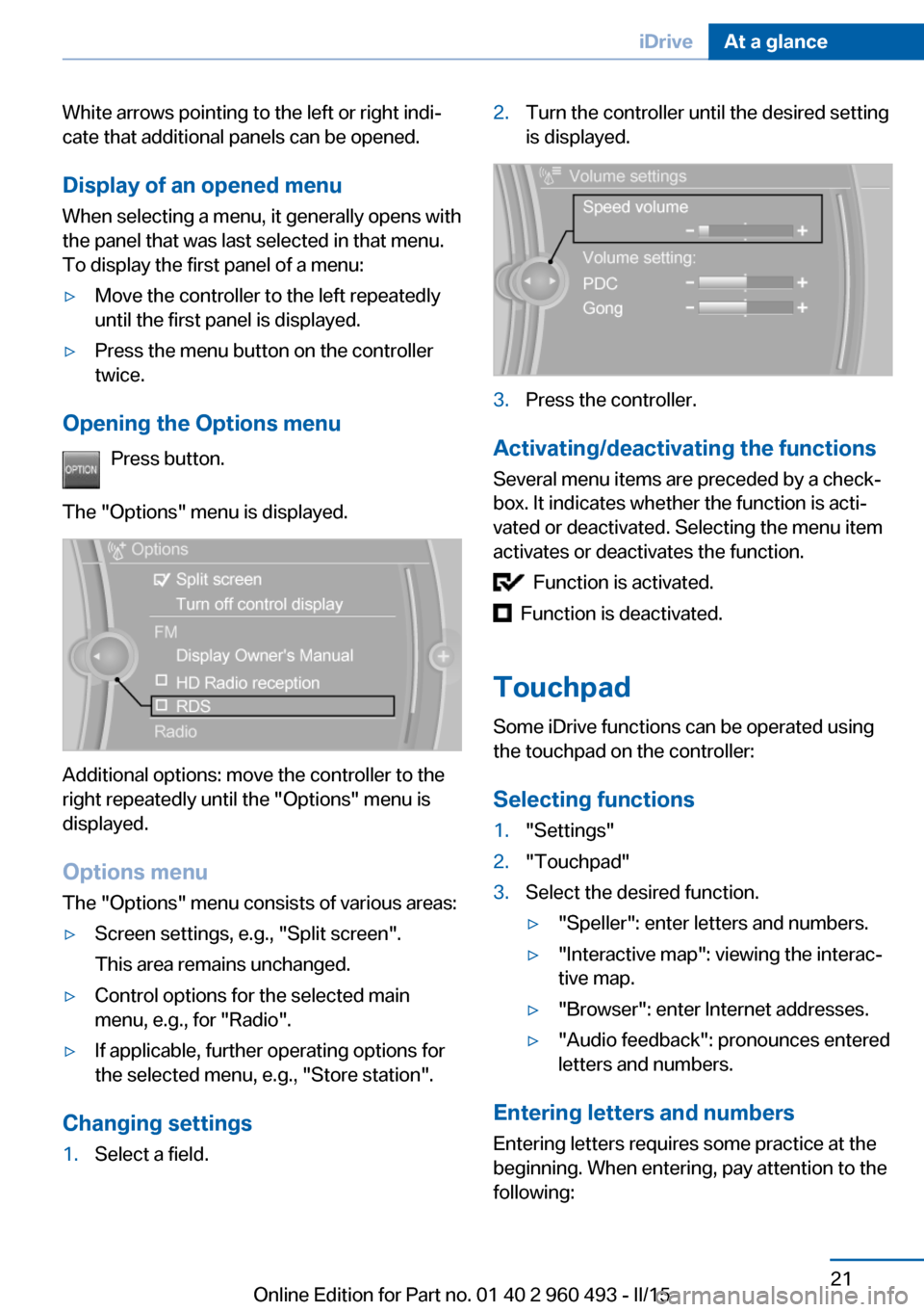
White arrows pointing to the left or right indi‐
cate that additional panels can be opened.
Display of an opened menu
When selecting a menu, it generally opens with
the panel that was last selected in that menu.
To display the first panel of a menu:▷Move the controller to the left repeatedly
until the first panel is displayed.▷Press the menu button on the controller
twice.
Opening the Options menu
Press button.
The "Options" menu is displayed.
Additional options: move the controller to the
right repeatedly until the "Options" menu is
displayed.
Options menu The "Options" menu consists of various areas:
▷Screen settings, e.g., "Split screen".
This area remains unchanged.▷Control options for the selected main
menu, e.g., for "Radio".▷If applicable, further operating options for
the selected menu, e.g., "Store station".
Changing settings
1.Select a field.2.Turn the controller until the desired setting
is displayed.3.Press the controller.
Activating/deactivating the functions
Several menu items are preceded by a check‐
box. It indicates whether the function is acti‐
vated or deactivated. Selecting the menu item
activates or deactivates the function.
Function is activated.
Function is deactivated.
Touchpad Some iDrive functions can be operated using
the touchpad on the controller:
Selecting functions
1."Settings"2."Touchpad"3.Select the desired function.▷"Speller": enter letters and numbers.▷"Interactive map": viewing the interac‐
tive map.▷"Browser": enter Internet addresses.▷"Audio feedback": pronounces entered
letters and numbers.
Entering letters and numbers
Entering letters requires some practice at the
beginning. When entering, pay attention to the
following:
Seite 21iDriveAt a glance21
Online Edition for Part no. 01 40 2 960 493 - II/15
Page 103 of 255
Knee airbagThe knee airbag supports the legs in a frontal
impact.
Protective action
Airbags are not triggered in every impact situa‐
tion, e.g., in less severe accidents or rear-end
collisions.
Information on how to ensure the optimal
protective effect of the airbags▷Keep at a distance from the airbags.▷Always grasp the steering wheel on the
steering wheel rim, holding your hands at
the 3 o'clock and 9 o'clock positions, to
keep the risk of injury to your hands or
arms as low as possible when the airbag is
triggered.▷There should be no person, animals, or ob‐
jects between an airbag and a person.▷Do not use the cover of the front airbag on
the front passenger side as a storage area.▷Dashboard and windshield on the front
passenger side must stay clear - do not at‐
tach adhesive labels or coverings and do
not attach brackets or cables, e. g., for GPS
devices or' mobile phones.▷Make sure that the front passenger is sit‐
ting correctly, i.e., keeps his or her feet and
legs in the footwell; otherwise, leg injuries
might occur when front airbag is activated.▷Do not place slip covers, seat cushions or
other objects on the front passenger seat
that are not approved specifically for seats
with integrated side airbags.▷Do not hang pieces of clothing, such as
jackets, over the backrests.▷Make sure that occupants keep their heads
away from the side airbag and do not rest
against the head airbag; otherwise, injuries
might occur when airbag is activated.▷Do not remove the airbag system.▷Do not remove the steering wheel.▷Do not apply adhesive materials to the air‐
bag cover panels, do not cover them or
modify them in any way.▷Never modify either the individual compo‐
nents or the wiring in the airbag system.
This also applies to steering wheel covers,
the dashboard, the seats, the roof pillars
and the sides of the roofliner.◀
Even when you follow all instructions very
closely, injury from contact with the airbags
cannot be ruled out in certain situations.
The ignition and inflation noise may lead to
short-term and, in most cases, temporary
hearing impairment in sensitive individuals.
Malfunction, deactivation and after de‐
ploying the airbags
Do not touch the individual components imme‐
diately after the system has been triggered;
otherwise, you may risk burns.
Only have the airbags checked, repaired or dis‐
mantled and the airbag generator scrapped by
the service center or an authorized repair shop
for handling explosives.
Non-professional attempts to service the sys‐
tem could lead to failure in an emergency or
unintentional activation of the airbag - both
may lead to injury.◀
Warnings and information on the airbags are also found on the sun visors.
Functional readiness of the airbag
system
When the ignition is reel on, the warn‐
ing lamp in the instrument cluster lights
up briefly and thereby indicates the op‐
erational readiness of the entire airbag system
and the belt tensioner.
Airbag system malfunctioning
▷Warning lamp does not come on when the
ignition is turned on.▷The warning lamp lights up continuously.Seite 99SafetyControls99
Online Edition for Part no. 01 40 2 960 493 - II/15
Page 164 of 255
Tilting
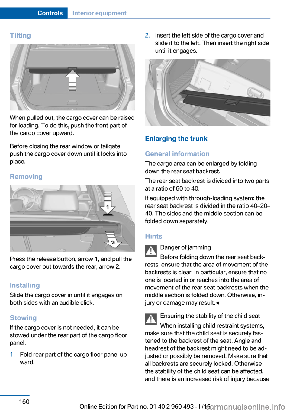
When pulled out, the cargo cover can be raised
for loading. To do this, push the front part of
the cargo cover upward.
Before closing the rear window or tailgate,
push the cargo cover down until it locks into
place.
Removing
Press the release button, arrow 1, and pull the
cargo cover out towards the rear, arrow 2.
Installing Slide the cargo cover in until it engages on
both sides with an audible click.
Stowing
If the cargo cover is not needed, it can be
stowed under the rear part of the cargo floor
panel.
1.Fold rear part of the cargo floor panel up‐
ward.2.Insert the left side of the cargo cover and
slide it to the left. Then insert the right side
until it engages.
Enlarging the trunk
General information
The cargo area can be enlarged by folding
down the rear seat backrest.
The rear seat backrest is divided into two parts
at a ratio of 60 to 40.
If equipped with through-loading system: the
rear seat backrest is divided in the ratio 40–20–
40. The sides and the middle section can be
folded down separately.
Hints Danger of jamming
Before folding down the rear seat back‐
rests, ensure that the area of movement of the
backrests is clear. In particular, ensure that no
one is located in or reaches into the area of
movement of the rear seat backrests when the
middle section is folded down. Otherwise, in‐
jury or damage may result.◀
Ensuring the stability of the child seat
When installing child restraint systems,
make sure that the child seat is securely fas‐
tened to the backrest of the seat. Angle and
headrest of the backrest might need to be ad‐
justed or possibly be removed. Make sure that
all backrests are securely locked. Otherwise
the stability of the child seat can be affected,
and there is an increased risk of injury because
Seite 160ControlsInterior equipment160
Online Edition for Part no. 01 40 2 960 493 - II/15
Page 171 of 255
3.Hook the retaining strap into the fixing
point.4.Press button 1 to tighten the retaining
strap.
To secure larger loads, the retaining straps can
also be interlocked with one another.
Removing the brackets
Pull the bracket vertically out of the fixing
point.
Stowing the adaptive retaining system If the adaptive retaining system is not needed,
it can be stowed under the rear part of the
cargo floor panel. Use the tension straps to se‐
cure it more firmly.
Floor net
The floor net can also be used to Secure the
load, refer to page 174, and to store small
parts.
Storage compartment under the cargofloor panel
Maximum load
To avoid damage to the vehicle, do not
exceed a maximum permitted load of 44 lbs/
20 kg in the storage compartment under the
cargo floor panel.◀
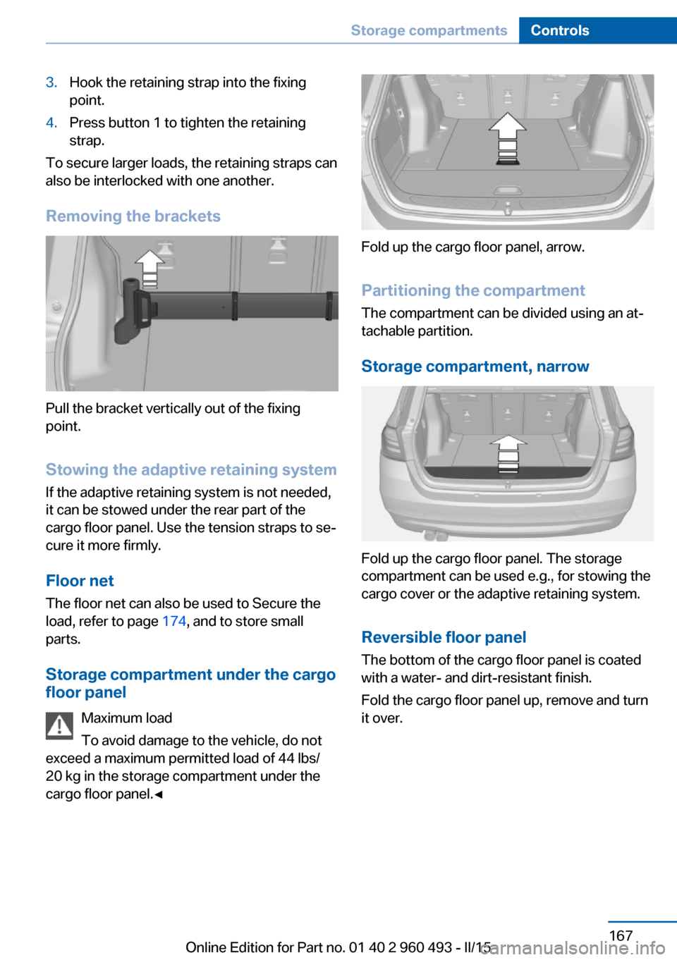
Fold up the cargo floor panel, arrow.
Partitioning the compartment The compartment can be divided using an at‐
tachable partition.
Storage compartment, narrow
Fold up the cargo floor panel. The storage
compartment can be used e.g., for stowing the
cargo cover or the adaptive retaining system.
Reversible floor panel
The bottom of the cargo floor panel is coated
with a water- and dirt-resistant finish.
Fold the cargo floor panel up, remove and turn
it over.
Seite 167Storage compartmentsControls167
Online Edition for Part no. 01 40 2 960 493 - II/15
Page 232 of 255
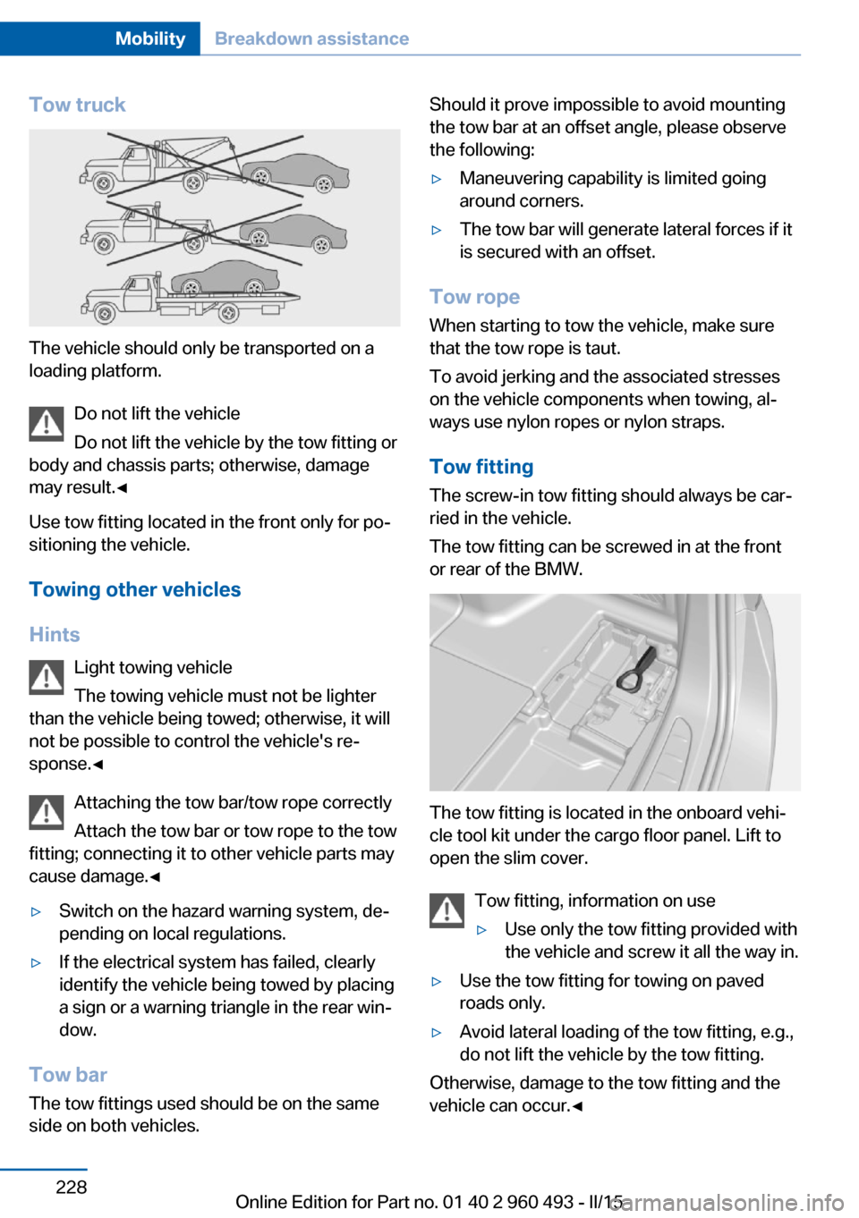
Tow truck
The vehicle should only be transported on a
loading platform.
Do not lift the vehicle
Do not lift the vehicle by the tow fitting or
body and chassis parts; otherwise, damage
may result.◀
Use tow fitting located in the front only for po‐
sitioning the vehicle.
Towing other vehicles
Hints Light towing vehicle
The towing vehicle must not be lighter
than the vehicle being towed; otherwise, it will
not be possible to control the vehicle's re‐
sponse.◀
Attaching the tow bar/tow rope correctly
Attach the tow bar or tow rope to the tow
fitting; connecting it to other vehicle parts may
cause damage.◀
▷Switch on the hazard warning system, de‐
pending on local regulations.▷If the electrical system has failed, clearly
identify the vehicle being towed by placing
a sign or a warning triangle in the rear win‐
dow.
Tow bar
The tow fittings used should be on the same
side on both vehicles.
Should it prove impossible to avoid mounting
the tow bar at an offset angle, please observe
the following:▷Maneuvering capability is limited going
around corners.▷The tow bar will generate lateral forces if it
is secured with an offset.
Tow rope
When starting to tow the vehicle, make sure
that the tow rope is taut.
To avoid jerking and the associated stresses
on the vehicle components when towing, al‐
ways use nylon ropes or nylon straps.
Tow fitting
The screw-in tow fitting should always be car‐
ried in the vehicle.
The tow fitting can be screwed in at the front
or rear of the BMW.
The tow fitting is located in the onboard vehi‐
cle tool kit under the cargo floor panel. Lift to
open the slim cover.
Tow fitting, information on use
▷Use only the tow fitting provided with
the vehicle and screw it all the way in.▷Use the tow fitting for towing on paved
roads only.▷Avoid lateral loading of the tow fitting, e.g.,
do not lift the vehicle by the tow fitting.
Otherwise, damage to the tow fitting and the
vehicle can occur.◀
Seite 228MobilityBreakdown assistance228
Online Edition for Part no. 01 40 2 960 493 - II/15