2016 BMW 3 SERIES SPORTS WAGON Tool
[x] Cancel search: ToolPage 13 of 255
cluding the manufacturer, using special diag‐
nostic tools. You can obtain further information
there if you need it. After an error is corrected,
the information in the fault memory is deleted
or overwritten on a continuous basis.
With the vehicle in use there are situations
where you can associate these technical data
with individuals if combined with other infor‐
mation, e.g., an accident report, damage to the
vehicle, eye witness accounts — possibly with
the assistance of an expert.
Additional functions that are contractually
agreed with the customer - such as vehicle
emergency locating - you can transmit certain
vehicle data from the vehicle.
Event Data Recorder EDR
This vehicle is equipped with an event data re‐
corder EDR. The main purpose of an EDR is to
record, in certain crash or near crash-like situa‐
tions, such as an air bag deployment or hitting
a road obstacle, data that will assist in under‐
standing how a vehicle’s systems performed.
The EDR is designed to record data related to
vehicle dynamics and safety systems for a
short period of time, typically 30 seconds or
less.
The EDR in this vehicle is designed to record
such data as:▷How various systems in your vehicle were
operating.▷Whether or not the driver and passenger
safety belts were fastened.▷How far, if at all, the driver was depressing
the accelerator and/or brake pedal.▷How fast the vehicle was traveling.
These data can help provide a better under‐
standing of the circumstances in which
crashes and injuries occur.
EDR data are recorded by your vehicle only if a
nontrivial crash situation occurs; no data are
recorded by the EDR under normal driving
conditions and no personal data, e.g., name,
gender, age, and crash location, are recorded.
However, other parties, such as law enforce‐
ment, could combine the EDR data with the
type of personally identifying data routinely ac‐
quired during a crash investigation.
To read data recorded by an EDR, special
equipment is required, and access to the vehi‐
cle or the EDR is needed. In addition to the ve‐
hicle manufacturer, other parties, such as law
enforcement, that have the special equipment,
can read the information if they have access to
the vehicle or the EDR.
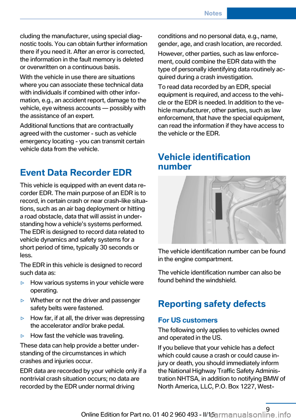
Vehicle identification
number
The vehicle identification number can be found
in the engine compartment.
The vehicle identification number can also be
found behind the windshield.
Reporting safety defects
For US customers The following only applies to vehicles owned
and operated in the US.
If you believe that your vehicle has a defect
which could cause a crash or could cause in‐
jury or death, you should immediately inform
the National Highway Traffic Safety Adminis‐
tration NHTSA, in addition to notifying BMW of
North America, LLC, P.O. Box 1227, West‐
Seite 9Notes9
Online Edition for Part no. 01 40 2 960 493 - II/15
Page 216 of 255
Replacing componentsVehicle features and optionsThis chapter describes all standard, country-
specific and optional features offered with the
series. It also describes features that are not
necessarily available in your car, e. g., due to
the selected options or country versions. This
also applies to safety-related functions and
systems. The respectively applicable country
provisions must be observed when using the
respective features and systems.
Onboard vehicle tool kit
The onboard vehicle tool kit is located under
the cargo floor panel. Lift to open the slim
cover.
Wiper blade replacement
Note Do not fold down the wipers without
wiper blades
Do not fold down the wipers if wiper blades
have not been installed; this may damage the
windshield.◀
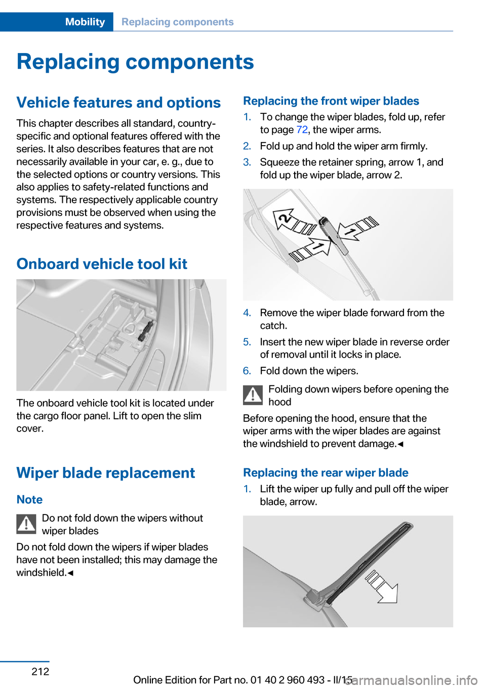
Replacing the front wiper blades1.To change the wiper blades, fold up, refer
to page 72, the wiper arms.2.Fold up and hold the wiper arm firmly.3.Squeeze the retainer spring, arrow 1, and
fold up the wiper blade, arrow 2.4.Remove the wiper blade forward from the
catch.5.Insert the new wiper blade in reverse order
of removal until it locks in place.6.Fold down the wipers.
Folding down wipers before opening the hood
Before opening the hood, ensure that the
wiper arms with the wiper blades are against
the windshield to prevent damage.◀
Replacing the rear wiper blade
1.Lift the wiper up fully and pull off the wiper
blade, arrow.Seite 212MobilityReplacing components212
Online Edition for Part no. 01 40 2 960 493 - II/15
Page 221 of 255
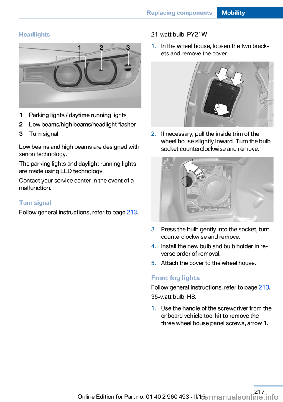
Headlights1Parking lights / daytime running lights2Low beams/high beams/headlight flasher3Turn signal
Low beams and high beams are designed with
xenon technology.
The parking lights and daylight running lights
are made using LED technology.
Contact your service center in the event of a
malfunction.
Turn signal
Follow general instructions, refer to page 213.
21-watt bulb, PY21W1.In the wheel house, loosen the two brack‐
ets and remove the cover.2.If necessary, pull the inside trim of the
wheel house slightly inward. Turn the bulb
socket counterclockwise and remove.3.Press the bulb gently into the socket, turn
counterclockwise and remove.4.Install the new bulb and bulb holder in re‐
verse order of removal.5.Attach the cover to the wheel house.
Front fog lights
Follow general instructions, refer to page 213.
35-watt bulb, H8.
1.Use the handle of the screwdriver from the
onboard vehicle tool kit to remove the
three wheel house panel screws, arrow 1.Seite 217Replacing componentsMobility217
Online Edition for Part no. 01 40 2 960 493 - II/15
Page 223 of 255
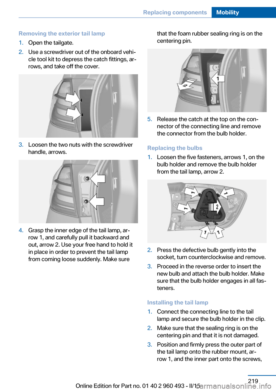
Removing the exterior tail lamp1.Open the tailgate.2.Use a screwdriver out of the onboard vehi‐
cle tool kit to depress the catch fittings, ar‐
rows, and take off the cover.3.Loosen the two nuts with the screwdriver
handle, arrows.4.Grasp the inner edge of the tail lamp, ar‐
row 1, and carefully pull it backward and
out, arrow 2. Use your free hand to hold it
in place in order to prevent the tail lamp
from coming loose suddenly. Make surethat the foam rubber sealing ring is on the
centering pin.5.Release the catch at the top on the con‐
nector of the connecting line and remove
the connector from the bulb holder.
Replacing the bulbs
1.Loosen the five fasteners, arrows 1, on the
bulb holder and remove the bulb holder
from the tail lamp, arrow 2.2.Press the defective bulb gently into the
socket, turn counterclockwise and remove.3.Proceed in the reverse order to insert the
new bulb and attach the bulb holder. Make
sure that the bulb holder engages in all fas‐
teners.
Installing the tail lamp
1.Connect the connecting line to the tail
lamp and secure the bulb holder in the clip.2.Make sure that the sealing ring is on the
centering pin and that it is not damaged.3.Position and firmly press the outer part of
the tail lamp onto the rubber mount, ar‐
row 1, and the inner part onto the screws,Seite 219Replacing componentsMobility219
Online Edition for Part no. 01 40 2 960 493 - II/15
Page 225 of 255
Changing wheels
Hints
When using run-flat tires or sealants, a tire
does not need to be changed immediately in
the event of pressure loss due to a flat tire.
Which is why no spare tire is available.
The tools for changing wheels are available as
accessories from your service center.
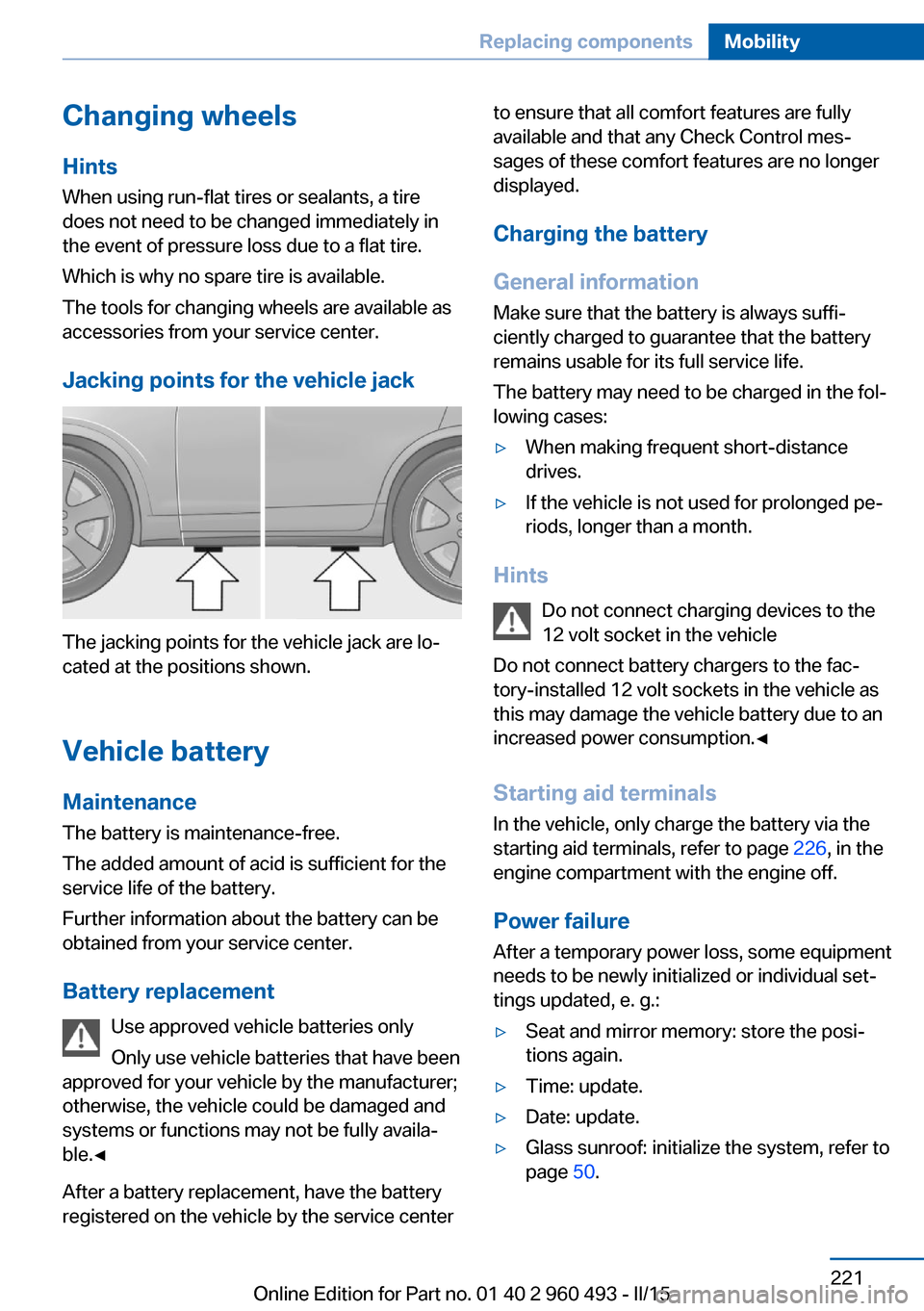
Jacking points for the vehicle jack
The jacking points for the vehicle jack are lo‐
cated at the positions shown.
Vehicle battery Maintenance
The battery is maintenance-free.
The added amount of acid is sufficient for the
service life of the battery.
Further information about the battery can be
obtained from your service center.
Battery replacement Use approved vehicle batteries only
Only use vehicle batteries that have been
approved for your vehicle by the manufacturer;
otherwise, the vehicle could be damaged and
systems or functions may not be fully availa‐
ble.◀
After a battery replacement, have the battery
registered on the vehicle by the service center
to ensure that all comfort features are fully
available and that any Check Control mes‐
sages of these comfort features are no longer
displayed.
Charging the battery
General information
Make sure that the battery is always suffi‐
ciently charged to guarantee that the battery
remains usable for its full service life.
The battery may need to be charged in the fol‐
lowing cases:▷When making frequent short-distance
drives.▷If the vehicle is not used for prolonged pe‐
riods, longer than a month.
Hints
Do not connect charging devices to the
12 volt socket in the vehicle
Do not connect battery chargers to the fac‐
tory-installed 12 volt sockets in the vehicle as
this may damage the vehicle battery due to an
increased power consumption.◀
Starting aid terminals
In the vehicle, only charge the battery via the
starting aid terminals, refer to page 226, in the
engine compartment with the engine off.
Power failure
After a temporary power loss, some equipment
needs to be newly initialized or individual set‐
tings updated, e. g.:
▷Seat and mirror memory: store the posi‐
tions again.▷Time: update.▷Date: update.▷Glass sunroof: initialize the system, refer to
page 50.Seite 221Replacing componentsMobility221
Online Edition for Part no. 01 40 2 960 493 - II/15
Page 226 of 255
Disposing of old batteriesHave old batteries disposed of by your
service center or bring them to a recy‐
cling center.
Maintain the battery in an upright position for
transport and storage. Secure the battery so
that it does not tip over during transport.
Fuses Hints Replacing fuses
Never attempt to repair a blown fuse and
do not replace a defective fuse with a substi‐
tute of another color or amperage rating; this
could lead to a circuit overload, ultimately re‐
sulting in a fire in the vehicle.◀
Plastic tweezers and information on the fuse
types and locations are stored in the fuse box
in the trunk.
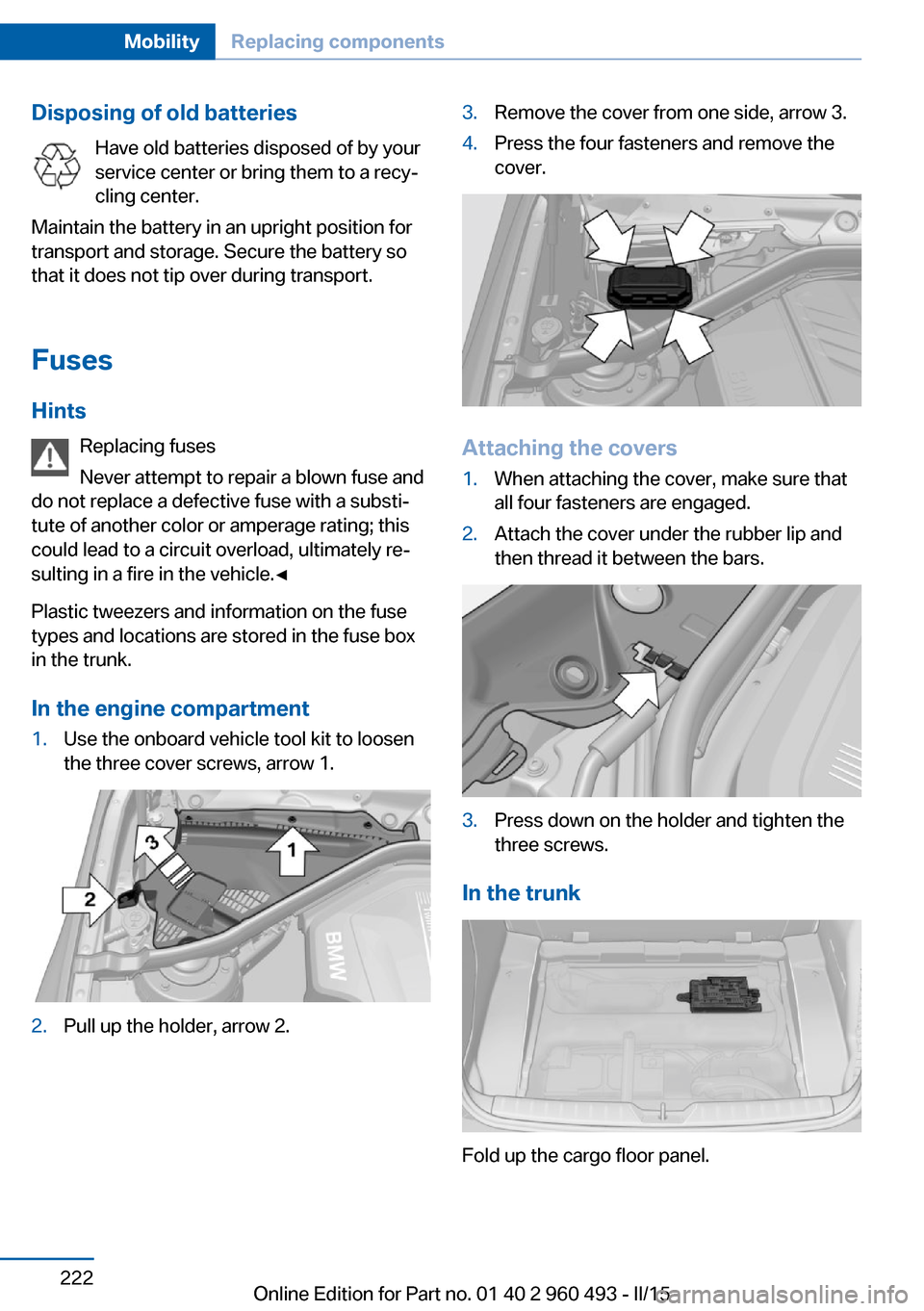
In the engine compartment1.Use the onboard vehicle tool kit to loosen
the three cover screws, arrow 1.2.Pull up the holder, arrow 2.3.Remove the cover from one side, arrow 3.4.Press the four fasteners and remove the
cover.
Attaching the covers
1.When attaching the cover, make sure that
all four fasteners are engaged.2.Attach the cover under the rubber lip and
then thread it between the bars.3.Press down on the holder and tighten the
three screws.
In the trunk
Fold up the cargo floor panel.
Seite 222MobilityReplacing components222
Online Edition for Part no. 01 40 2 960 493 - II/15
Page 232 of 255
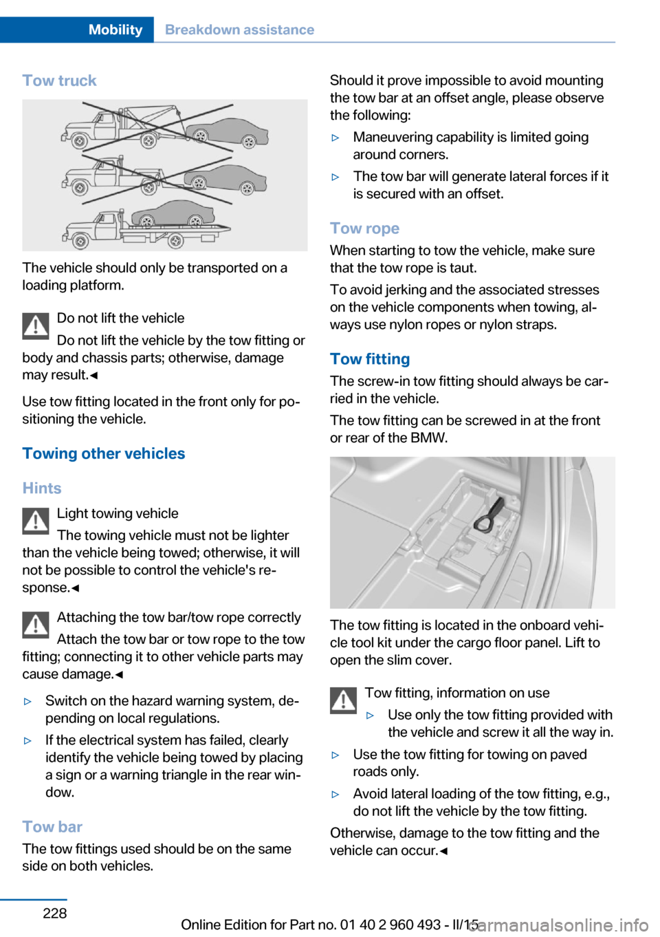
Tow truck
The vehicle should only be transported on a
loading platform.
Do not lift the vehicle
Do not lift the vehicle by the tow fitting or
body and chassis parts; otherwise, damage
may result.◀
Use tow fitting located in the front only for po‐
sitioning the vehicle.
Towing other vehicles
Hints Light towing vehicle
The towing vehicle must not be lighter
than the vehicle being towed; otherwise, it will
not be possible to control the vehicle's re‐
sponse.◀
Attaching the tow bar/tow rope correctly
Attach the tow bar or tow rope to the tow
fitting; connecting it to other vehicle parts may
cause damage.◀
▷Switch on the hazard warning system, de‐
pending on local regulations.▷If the electrical system has failed, clearly
identify the vehicle being towed by placing
a sign or a warning triangle in the rear win‐
dow.
Tow bar
The tow fittings used should be on the same
side on both vehicles.
Should it prove impossible to avoid mounting
the tow bar at an offset angle, please observe
the following:▷Maneuvering capability is limited going
around corners.▷The tow bar will generate lateral forces if it
is secured with an offset.
Tow rope
When starting to tow the vehicle, make sure
that the tow rope is taut.
To avoid jerking and the associated stresses
on the vehicle components when towing, al‐
ways use nylon ropes or nylon straps.
Tow fitting
The screw-in tow fitting should always be car‐
ried in the vehicle.
The tow fitting can be screwed in at the front
or rear of the BMW.
The tow fitting is located in the onboard vehi‐
cle tool kit under the cargo floor panel. Lift to
open the slim cover.
Tow fitting, information on use
▷Use only the tow fitting provided with
the vehicle and screw it all the way in.▷Use the tow fitting for towing on paved
roads only.▷Avoid lateral loading of the tow fitting, e.g.,
do not lift the vehicle by the tow fitting.
Otherwise, damage to the tow fitting and the
vehicle can occur.◀
Seite 228MobilityBreakdown assistance228
Online Edition for Part no. 01 40 2 960 493 - II/15
Page 249 of 255

Lights and bulbs 213
Light switch 93
Load 174
Loading 173
Lock, door 39
Locking/unlocking via door lock 39
Locking/unlocking with re‐ mote control 37
Locking, automatic 45
Locking, settings 45
Lock, power window 48
Locks, doors, and win‐ dows 64
Low beams 93
Low beams, automatic, refer to High-beam Assistant 95
Lower back support 53
Low-Sulfur Diesel 189
Luggage rack, see Roof- mounted luggage rack 175
Lumbar support 53
M
Maintenance 210
Maintenance require‐ ments 210
Maintenance, service require‐ ments 84
Maintenance system, BMW 210
Make-up mirror 157
Malfunction displays, see Check Control 79
Manual air distribu‐ tion 147, 150
Manual air flow 147, 150
Manual mode, Steptronic transmission 75
Manual operation, door lock 39
Manual operation, exterior mirrors 59
Manual operation, fuel filler flap 186 Manual operation, Park Dis‐
tance Control PDC 134
Manual operation, rearview camera 137
Manual operation, Side View 139
Manual operation, Top View 140
Manual transmission 73
Marking on approved tires 198
Marking, run-flat tires 199
Master key, refer to Remote control 34
Maximum cooling 149
Maximum speed, display 86
Maximum speed, winter tires 199
Measure, units of 91
Medical kit 225
Memory, seat, mirror 57
Menu, EfficientDynamics 180
Menu in instrument clus‐ ter 87
Menus, operating, iDrive 18
Menus, refer to iDrive operat‐ ing concept 20
Messages, see Check Con‐ trol 79
Microfilter 148, 151
Minimum tread, tires 197
Mirror 58
Mirror memory 57
Mobile communication devi‐ ces in the vehicle 171
Mobility System 199
Modifications, technical, refer to Safety 7
Moisture in headlight 213
Monitor, refer to Control Dis‐ play 18
Mounting of child restraint systems 61
Multifunction steering wheel, buttons 14 N
Navigation, see user's manual for Navigation, Entertain‐
ment and Communication
Neck restraints, front, refer to Head restraints 55
Neck restraints, rear, refer to Head restraints 56
Neutral cleaner, see wheel cleaner 232
New wheels and tires 198
Nylon rope for tow-starting/ towing 228
O OBD Onboard Diagnosis 211
OBD, see OBD Onboard Di‐ agnosis 211
Obstacle marking, rearview camera 137
Octane rating, refer to Rec‐ ommended fuel grade 188
Odometer 83
Office, see user's manual for Navigation, Entertainment
and Communication
Oil 206
Oil, adding 207
Oil additives 208
Oil change 208
Oil change interval, service requirements 84
Oil filler neck 207
Oil types, alternative 208
Oil types, approved 208
Old batteries, disposal 222
On-board computer 87
Onboard monitor, refer to Control Display 18
Onboard vehicle tool kit 212
Opening/closing via door lock 39
Opening and closing 34 Seite 245Everything from A to ZReference245
Online Edition for Part no. 01 40 2 960 493 - II/15