2016 BMW 3 SERIES SPORTS WAGON replace
[x] Cancel search: replacePage 108 of 255
▷The tire inflation pressure has fallen below
the level of the last confirmation.
In this case:
▷Check the tire pressure and correct as
needed.▷Carry out a reset of the system after a tire
change.
System limits
The system does not function properly if a re‐
set has not been carried out, e.g., a flat tire is
reported though tire inflation pressures are
correct.
The tire inflation pressure depends on the
tire's temperature. Driving or exposure to the
sun will increase the tire's temperature, thus
increasing the tire inflation pressure. The tire
inflation pressure is reduced when the tire
temperature falls again. These circumstances
may cause a warning when temperatures fall
very sharply.
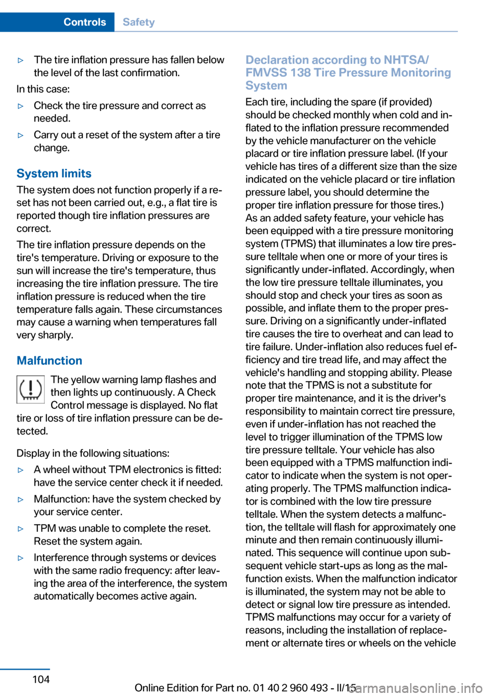
Malfunction The yellow warning lamp flashes and
then lights up continuously. A Check
Control message is displayed. No flat
tire or loss of tire inflation pressure can be de‐
tected.
Display in the following situations:
▷A wheel without TPM electronics is fitted:
have the service center check it if needed.▷Malfunction: have the system checked by
your service center.▷TPM was unable to complete the reset.
Reset the system again.▷Interference through systems or devices
with the same radio frequency: after leav‐
ing the area of the interference, the system
automatically becomes active again.Declaration according to NHTSA/
FMVSS 138 Tire Pressure Monitoring
System
Each tire, including the spare (if provided)
should be checked monthly when cold and in‐
flated to the inflation pressure recommended
by the vehicle manufacturer on the vehicle
placard or tire inflation pressure label. (If your
vehicle has tires of a different size than the size
indicated on the vehicle placard or tire inflation
pressure label, you should determine the
proper tire inflation pressure for those tires.)
As an added safety feature, your vehicle has
been equipped with a tire pressure monitoring
system (TPMS) that illuminates a low tire pres‐
sure telltale when one or more of your tires is
significantly under-inflated. Accordingly, when
the low tire pressure telltale illuminates, you
should stop and check your tires as soon as
possible, and inflate them to the proper pres‐
sure. Driving on a significantly under-inflated
tire causes the tire to overheat and can lead to
tire failure. Under-inflation also reduces fuel ef‐
ficiency and tire tread life, and may affect the
vehicle's handling and stopping ability. Please
note that the TPMS is not a substitute for
proper tire maintenance, and it is the driver's
responsibility to maintain correct tire pressure,
even if under-inflation has not reached the
level to trigger illumination of the TPMS low
tire pressure telltale. Your vehicle has also
been equipped with a TPMS malfunction indi‐
cator to indicate when the system is not oper‐
ating properly. The TPMS malfunction indica‐
tor is combined with the low tire pressure
telltale. When the system detects a malfunc‐
tion, the telltale will flash for approximately one
minute and then remain continuously illumi‐
nated. This sequence will continue upon sub‐
sequent vehicle start-ups as long as the mal‐
function exists. When the malfunction indicator
is illuminated, the system may not be able to
detect or signal low tire pressure as intended.
TPMS malfunctions may occur for a variety of
reasons, including the installation of replace‐
ment or alternate tires or wheels on the vehicleSeite 104ControlsSafety104
Online Edition for Part no. 01 40 2 960 493 - II/15
Page 109 of 255
that prevent the TPMS from functioning prop‐
erly. Always check the TPMS malfunction tell‐
tale after replacing one or more tires or wheels
on your vehicle to ensure that the replacement
or alternate tires and wheels allow the TPMS
to continue to function properly.
FTM Flat Tire Monitor The conceptThe system detects tire inflation pressure losson the basis of rotation speed differences be‐
tween the individual wheels while driving.
In the event of a tire inflation pressure loss, the
diameter and therefore the rotational speed of
the corresponding wheel changes. This will be
detected and reported as a flat tire.
The system does not measure the actual infla‐
tion pressure in the tires.
Functional requirements
The system must have been initialized when
the tire inflation pressure was correct; other‐
wise, reliable flagging of a flat tire is not as‐
sured. Initialize the system after each correc‐ tion of the tire inflation pressure and after
every tire or wheel change.
Status display
The current status of the Flat Tire Monitor can
be displayed on the Control Display, e.g.,
whether or not the FTM is active.
On the Control Display:1."Vehicle info"2."Vehicle status"3. "Flat Tire Monitor (FTM)"
The status is displayed.
Initialization
When initializing the once set inflation tire
pressures serve as reference values in order to
detect a flat tire. Initialization is started by con‐
firming the tire inflation pressures.
Do not initialize the system when driving with
snow chains.
On the Control Display:1."Vehicle info"2."Vehicle status"3. "Perform reset"4.Start the engine - do not drive off.5.Start the initialization with "Perform reset".6.Drive away.
The initialization is completed while driving,
which can be interrupted at any time.
The initialization automatically continues when
driving resumes.
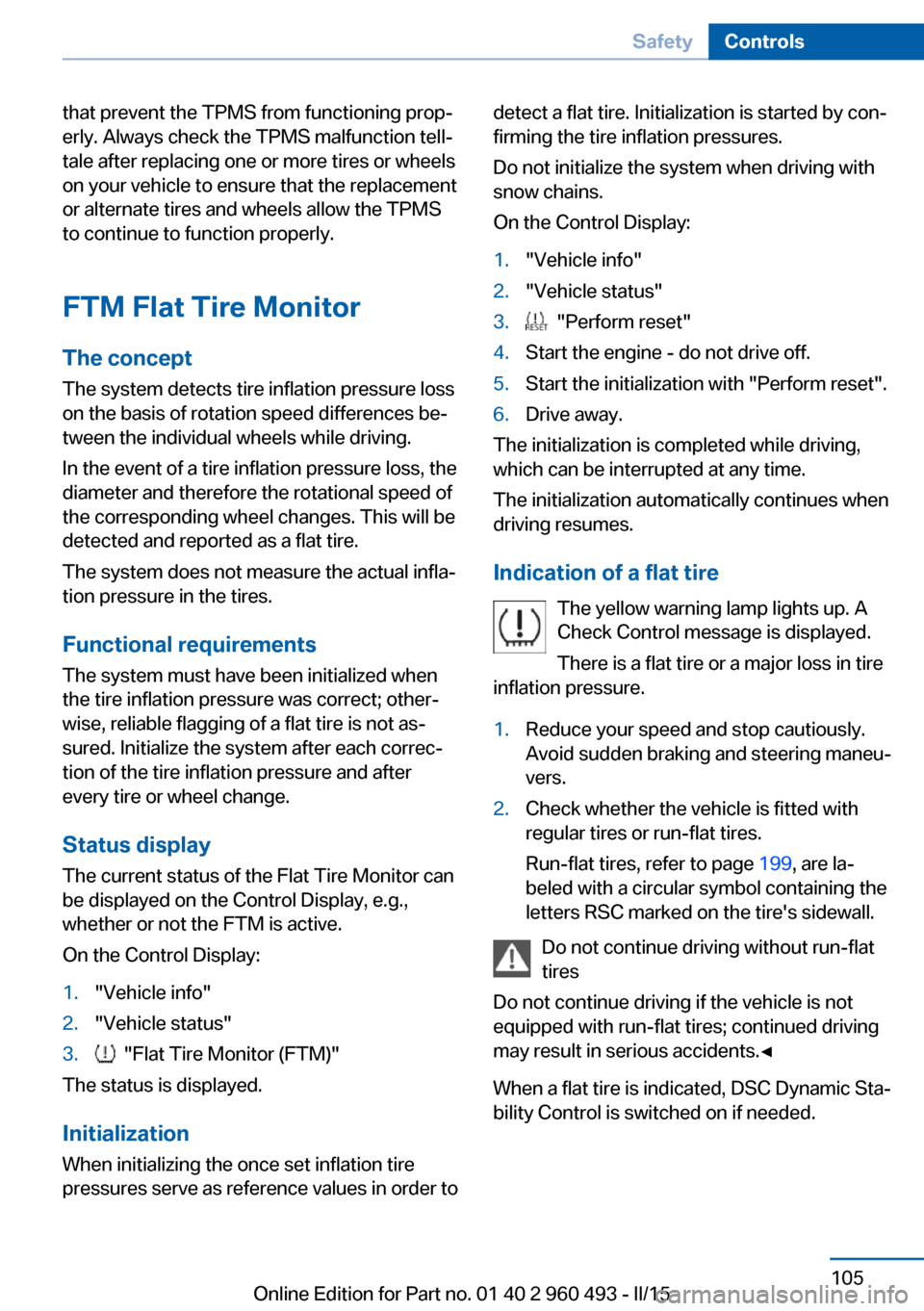
Indication of a flat tire The yellow warning lamp lights up. A
Check Control message is displayed.
There is a flat tire or a major loss in tire
inflation pressure.
1.Reduce your speed and stop cautiously.
Avoid sudden braking and steering maneu‐
vers.2.Check whether the vehicle is fitted with
regular tires or run-flat tires.
Run-flat tires, refer to page 199, are la‐
beled with a circular symbol containing the
letters RSC marked on the tire's sidewall.
Do not continue driving without run-flat
tires
Do not continue driving if the vehicle is not
equipped with run-flat tires; continued driving
may result in serious accidents.◀
When a flat tire is indicated, DSC Dynamic Sta‐
bility Control is switched on if needed.
Seite 105SafetyControls105
Online Edition for Part no. 01 40 2 960 493 - II/15
Page 152 of 255
Press button repeatedly to select an
operating mode:▷LED off: outside air flows in continuously.▷LED on, recirculated-air mode: the supply
of outside air into the vehicle is perma‐
nently blocked.
Recirculated air mode switches off automati‐
cally at low external temperatures after a cer‐
tain amount of time in order to avoid window
fogging.
If the windows fog over, switch off recircu‐
lated-air mode and increase the air flow, if
needed.
Sufficient ventilation
When remaining in the vehicle for an ex‐
tended period of time, ensure sufficient exter‐
nal ventilation. Do not continuously use recir‐
culated-air mode; otherwise the air quality in
the interior continuously deteriorates and win‐
dow condensation increases.◀
Switching the system on/off
Switch off Press the left button for the minimum
speed.
Switching on
Press any button except▷Rear window defroster.▷Seat heating.
Microfilter
In external and recirculated air mode the mi‐
crofilter filters dust and pollen from the air.
This filter should be replaced during scheduled
maintenance, refer to page 210, of your vehi‐
cle.
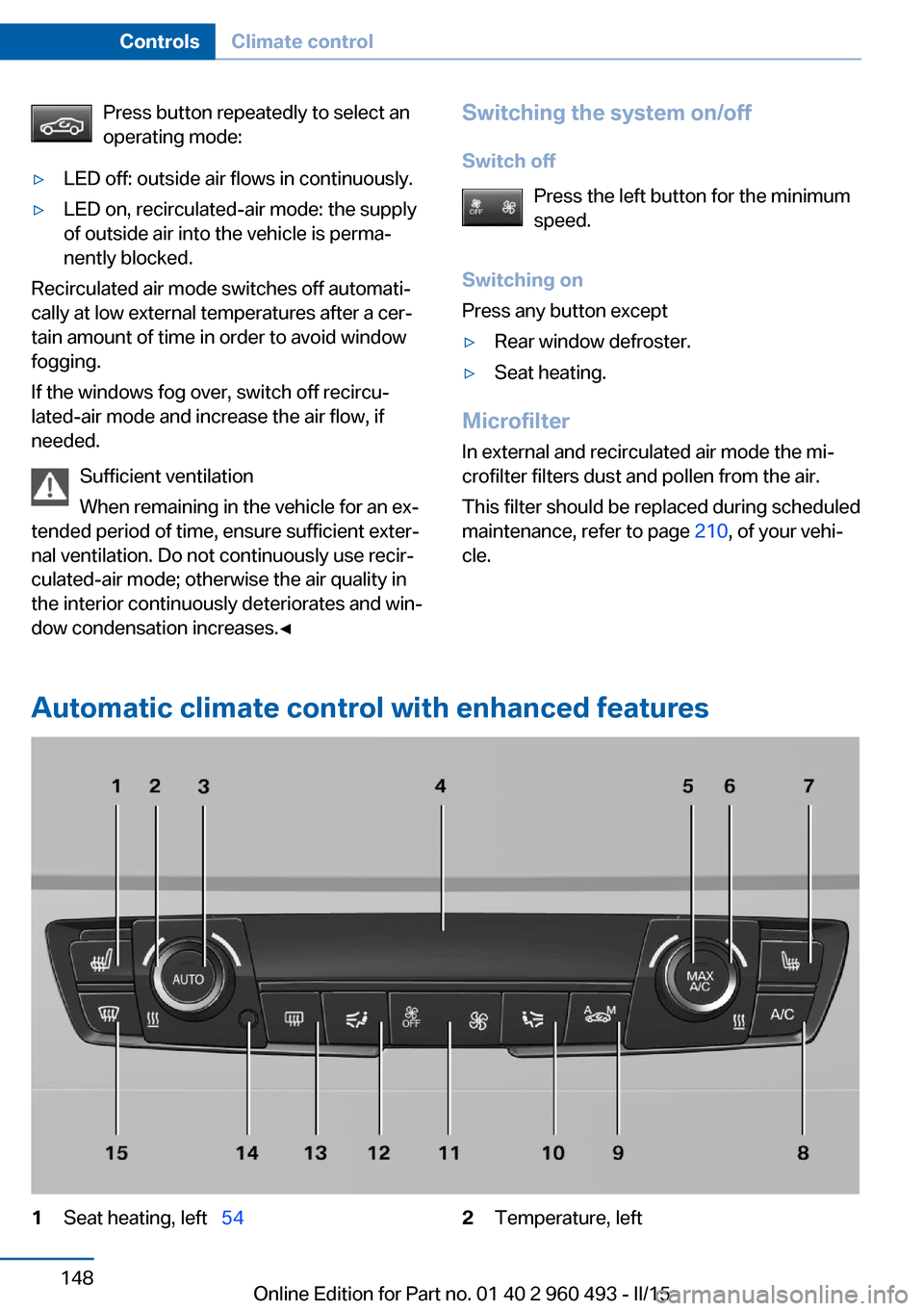
Automatic climate control with enhanced features
1Seat heating, left 542Temperature, leftSeite 148ControlsClimate control148
Online Edition for Part no. 01 40 2 960 493 - II/15
Page 155 of 255
Defrosts windows and removes
condensation
Press button.
Ice and condensation are quickly re‐
moved from the windshield and the front side
windows.
For this purpose, point the side vents onto the
side windows as needed.
Adjust air flow with the program active.
If the windows are fogged over, you can also
switch on the cooling function or press the AUTO button to utilize the condensation sen‐
sor.
Switching the system on/off Switch off Press the left button for the minimum
speed.
Switching on
Press any button except▷Rear window defroster.▷Seat heating.
Microfilter/activated-charcoal filter
In external and recirculated air mode the mi‐
crofilter/activated charcoal filter filters dust,
pollen, and gaseous pollutants out of the air.
This filter should be replaced during scheduled
maintenance, refer to page 210, of your vehi‐
cle.
Ventilation
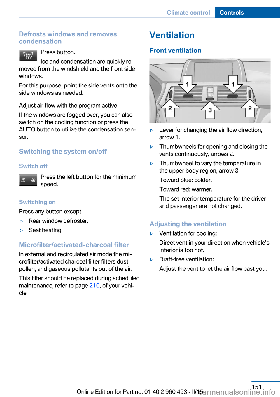
Front ventilation▷Lever for changing the air flow direction,
arrow 1.▷Thumbwheels for opening and closing the
vents continuously, arrows 2.▷Thumbwheel to vary the temperature in
the upper body region, arrow 3.
Toward blue: colder.
Toward red: warmer.
The set interior temperature for the driver
and passenger are not changed.
Adjusting the ventilation
▷Ventilation for cooling:
Direct vent in your direction when vehicle's
interior is too hot.▷Draft-free ventilation:
Adjust the vent to let the air flow past you.Seite 151Climate controlControls151
Online Edition for Part no. 01 40 2 960 493 - II/15
Page 160 of 255
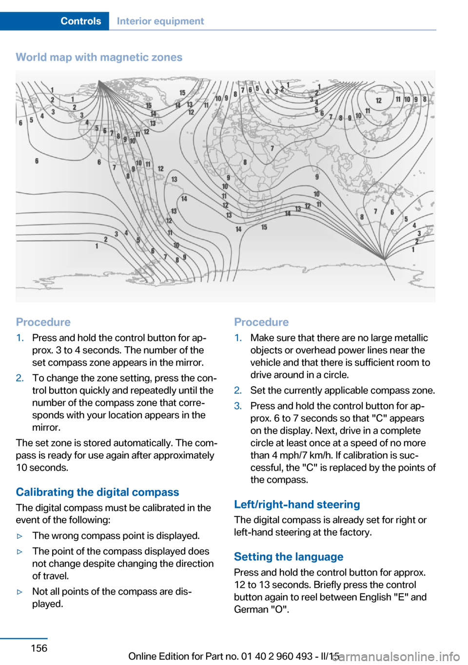
World map with magnetic zonesProcedure1.Press and hold the control button for ap‐
prox. 3 to 4 seconds. The number of the
set compass zone appears in the mirror.2.To change the zone setting, press the con‐
trol button quickly and repeatedly until the
number of the compass zone that corre‐
sponds with your location appears in the
mirror.
The set zone is stored automatically. The com‐
pass is ready for use again after approximately
10 seconds.
Calibrating the digital compass
The digital compass must be calibrated in the
event of the following:
▷The wrong compass point is displayed.▷The point of the compass displayed does
not change despite changing the direction
of travel.▷Not all points of the compass are dis‐
played.Procedure1.Make sure that there are no large metallic
objects or overhead power lines near the
vehicle and that there is sufficient room to
drive around in a circle.2.Set the currently applicable compass zone.3.Press and hold the control button for ap‐
prox. 6 to 7 seconds so that "C" appears
on the display. Next, drive in a complete
circle at least once at a speed of no more
than 4 mph/7 km/h. If calibration is suc‐
cessful, the "C" is replaced by the points of
the compass.
Left/right-hand steering
The digital compass is already set for right or
left-hand steering at the factory.
Setting the language
Press and hold the control button for approx.
12 to 13 seconds. Briefly press the control
button again to reel between English "E" and
German "O".
Seite 156ControlsInterior equipment156
Online Edition for Part no. 01 40 2 960 493 - II/15
Page 161 of 255
Settings are stored automatically after approxi‐
mately 10 seconds.
Sun visor
Glare shield Fold the sun visor down or up.
Vanity mirror A vanity mirror is located in the sun visor be‐
hind a cover. When the cover is opened, the
mirror lighting switches on.
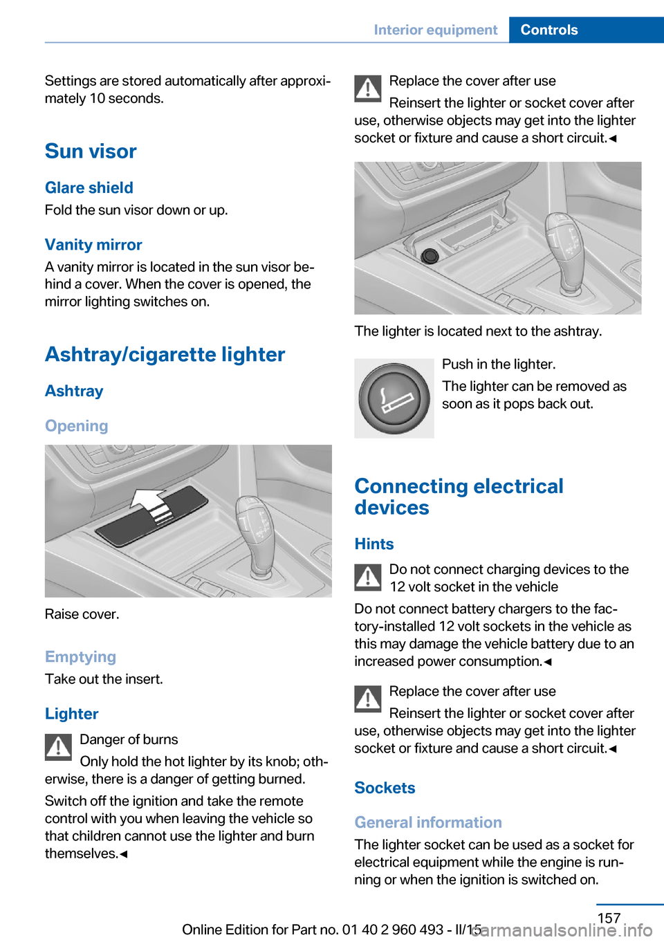
Ashtray/cigarette lighterAshtray
Opening
Raise cover.
EmptyingTake out the insert.
Lighter Danger of burns
Only hold the hot lighter by its knob; oth‐
erwise, there is a danger of getting burned.
Switch off the ignition and take the remote
control with you when leaving the vehicle so
that children cannot use the lighter and burn
themselves.◀
Replace the cover after use
Reinsert the lighter or socket cover after
use, otherwise objects may get into the lighter
socket or fixture and cause a short circuit.◀
The lighter is located next to the ashtray.
Push in the lighter.
The lighter can be removed as
soon as it pops back out.
Connecting electrical devices
Hints Do not connect charging devices to the
12 volt socket in the vehicle
Do not connect battery chargers to the fac‐
tory-installed 12 volt sockets in the vehicle as
this may damage the vehicle battery due to an
increased power consumption.◀
Replace the cover after use
Reinsert the lighter or socket cover after
use, otherwise objects may get into the lighter
socket or fixture and cause a short circuit.◀
Sockets
General information
The lighter socket can be used as a socket for
electrical equipment while the engine is run‐ ning or when the ignition is switched on.
Seite 157Interior equipmentControls157
Online Edition for Part no. 01 40 2 960 493 - II/15
Page 174 of 255
Things to remember when drivingVehicle features and options
This chapter describes all standard, country-
specific and optional features offered with the
series. It also describes features that are not
necessarily available in your car, e. g., due to
the selected options or country versions. This
also applies to safety-related functions and
systems. The respectively applicable country
provisions must be observed when using the
respective features and systems.
Breaking-in period General information
Moving parts need time to adjust to one an‐
other (break-in time).
The following instructions will help accomplish
a long vehicle life and good efficiency.
During break-in, do not use the Launch Con‐
trol, refer to page 76.
Engine, transmission, and axle drive
Up to 1,200 miles/2,000 km
Do not exceed the maximum engine and road
speed:▷For gasoline engine 4,500 rpm and
100 mph/160 km/h.▷For diesel engine 3,500 rpm and
93 mph/150 km/h.
Avoid full load or kickdown under all circum‐
stances.
From 1,200 miles/2,000 km The engine and vehicle speed can gradually be
increased.
Tires
Tire traction is not optimal due to manufactur‐
ing circumstances when tires are brand-new;
they achieve their full traction potential after a
break-in time.
Drive conservatively for the first
200 miles/300 km.
Brake system
Brakes require an initial break-in period of ap‐
prox. 300 miles/500 km to achieve optimal per‐
formance between brake discs and brake
pads. Drive moderately during this break-in pe‐
riod.
Clutch The function of the clutch reaches its optimal
level only after a distance driven of approx.
300 miles/500 km. During this break-in period,
engage the clutch gently.
Following part replacement
The same break-in procedures should be ob‐
served if any of the components above-men‐
tioned have to be renewed in the course of the
vehicle's operating life.
General driving notes
Closing the rear window and tailgate Drive with the rear window and tailgate
closed
Only drive with the tailgate closed; otherwise,
in the event of an accident or braking and eva‐
sive maneuvers, passengers and other traffic
may be injured, and the vehicle may be dam‐ aged. In addition, exhaust fumes may enter the
vehicle interior.◀Seite 170Driving tipsThings to remember when driving170
Online Edition for Part no. 01 40 2 960 493 - II/15
Page 195 of 255
exhaust fluid can be replenished simply
and safely.▷Alternative: NOx reduction agent AUS 32
Diesel exhaust fluid can be purchased at your
service center.
Refill quantity
When the Reserve display starts, add at least
3 bottles of reducing agent.
This corresponds to approx. 1.5 US gal/6 liters.
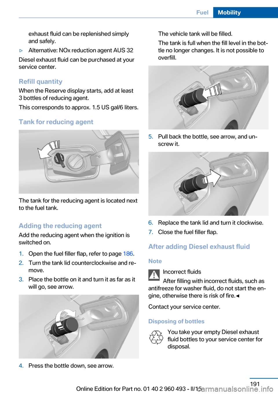
Tank for reducing agent
The tank for the reducing agent is located next
to the fuel tank.
Adding the reducing agent Add the reducing agent when the ignition is
switched on.
1.Open the fuel filler flap, refer to page 186.2.Turn the tank lid counterclockwise and re‐
move.3.Place the bottle on it and turn it as far as it
will go, see arrow.4.Press the bottle down, see arrow.The vehicle tank will be filled.
The tank is full when the fill level in the bot‐
tle no longer changes. It is not possible to
overfill.5.Pull back the bottle, see arrow, and un‐
screw it.6.Replace the tank lid and turn it clockwise.7.Close the fuel filler flap.
After adding Diesel exhaust fluid
Note Incorrect fluids
After filling with incorrect fluids, such as
antifreeze for washer fluid, do not start the en‐
gine, otherwise there is risk of fire.◀
Contact your service center.
Disposing of bottles You take your empty Diesel exhaust
fluid bottles to your service center for
disposal.
Seite 191FuelMobility191
Online Edition for Part no. 01 40 2 960 493 - II/15