2016 BMW 3 SERIES SPORTS WAGON information signal
[x] Cancel search: information signalPage 133 of 255

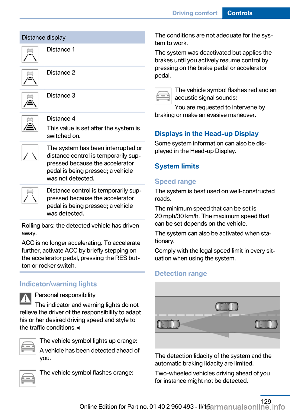
Distance displayDistance 1Distance 2Distance 3Distance 4
This value is set after the system is
switched on.The system has been interrupted or
distance control is temporarily sup‐
pressed because the accelerator
pedal is being pressed; a vehicle
was not detected.Distance control is temporarily sup‐
pressed because the accelerator
pedal is being pressed; a vehicle
was detected.Rolling bars: the detected vehicle has driven
away.
ACC is no longer accelerating. To accelerate
further, activate ACC by briefly stepping on
the accelerator pedal, pressing the RES but‐
ton or rocker switch.
Indicator/warning lights
Personal responsibility
The indicator and warning lights do not
relieve the driver of the responsibility to adapt
his or her desired driving speed and style to
the traffic conditions.◀
The vehicle symbol lights up orange:
A vehicle has been detected ahead of
you.
The vehicle symbol flashes orange:
The conditions are not adequate for the sys‐
tem to work.
The system was deactivated but applies the
brakes until you actively resume control by
pressing on the brake pedal or accelerator
pedal.
The vehicle symbol flashes red and an
acoustic signal sounds:
You are requested to intervene by
braking or make an evasive maneuver.
Displays in the Head-up Display Some system information can also be dis‐
played in the Head-up Display.
System limits
Speed range The system is best used on well-constructed
roads.
The minimum speed that can be set is
20 mph/30 km/h. The maximum speed that
can be set depends on the vehicle.
The system can also be activated when sta‐
tionary.
Comply with the legal speed limit in every sit‐
uation when using the system.
Detection range
The detection lidacity of the system and the
automatic braking lidacity are limited.
Two-wheeled vehicles driving ahead of you
for instance might not be detected.
Seite 129Driving comfortControls129
Online Edition for Part no. 01 40 2 960 493 - II/15
Page 137 of 255

When cruise control is maintained or stored,
DSC Dynamic Stability Control will be turned
on if needed.
Changing the speed
Press the rocker switch up or down repeatedly
until the desired speed is set.
If active, the displayed speed is stored and the
vehicle reaches the stored speed when the
road is clear.▷Each time the rocker switch is pressed to
the point of resistance, the desired speed
increases or decreases by approx.
1 mph/1 km/h.▷Each time the rocker switch is pressed
past the point of resistance, the desired
speed increases or decreases by a maxi‐
mum of 5 mph/10 km/h.
The maximum speed that can be set de‐
pends on the vehicle.▷Pressing the rocker switch to the resist‐
ance point and holding it accelerates or de‐
celerates the vehicle without requiring
pressure on the accelerator pedal.
After the rocker switch is released, the ve‐
hicle maintains its final speed. Pressing the
switch beyond the resistance point causes
the vehicle to accelerate more rapidly.
Resuming the desired speed
Press button.
The stored speed is reached and maintained. Displays in the instrument cluster
Indicator lamp Depending on how the vehicle is equip‐
ped, the indicator lamp in the instru‐
ment cluster indicates whether the sys‐
tem is switched on.
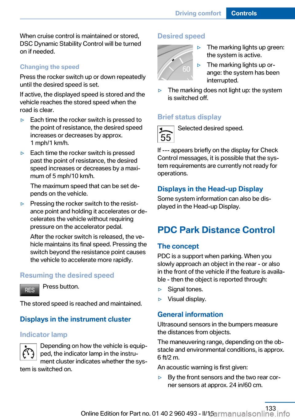
Desired speed▷The marking lights up green:
the system is active.▷The marking lights up or‐
ange: the system has been
interrupted.▷The marking does not light up: the system
is switched off.
Brief status display
Selected desired speed.
If --- appears briefly on the display for Check
Control messages, it is possible that the sys‐
tem requirements are currently not ready for
operations.
Displays in the Head-up Display Some system information can also be dis‐played in the Head-up Display.
PDC Park Distance Control
The concept PDC is a support when parking. When you
slowly approach an object in the rear - or also
in the front of the vehicle if the feature is availa‐
ble - then the object is reported through:
▷Signal tones.▷Visual display.
General information
Ultrasound sensors in the bumpers measure
the distances from objects.
The maneuvering range, depending on the ob‐
stacle and environmental conditions, is approx.
6 ft/2 m.
An acoustic warning is first given:
▷By the front sensors and the two rear cor‐
ner sensors at approx. 24 in/60 cm.Seite 133Driving comfortControls133
Online Edition for Part no. 01 40 2 960 493 - II/15
Page 222 of 255

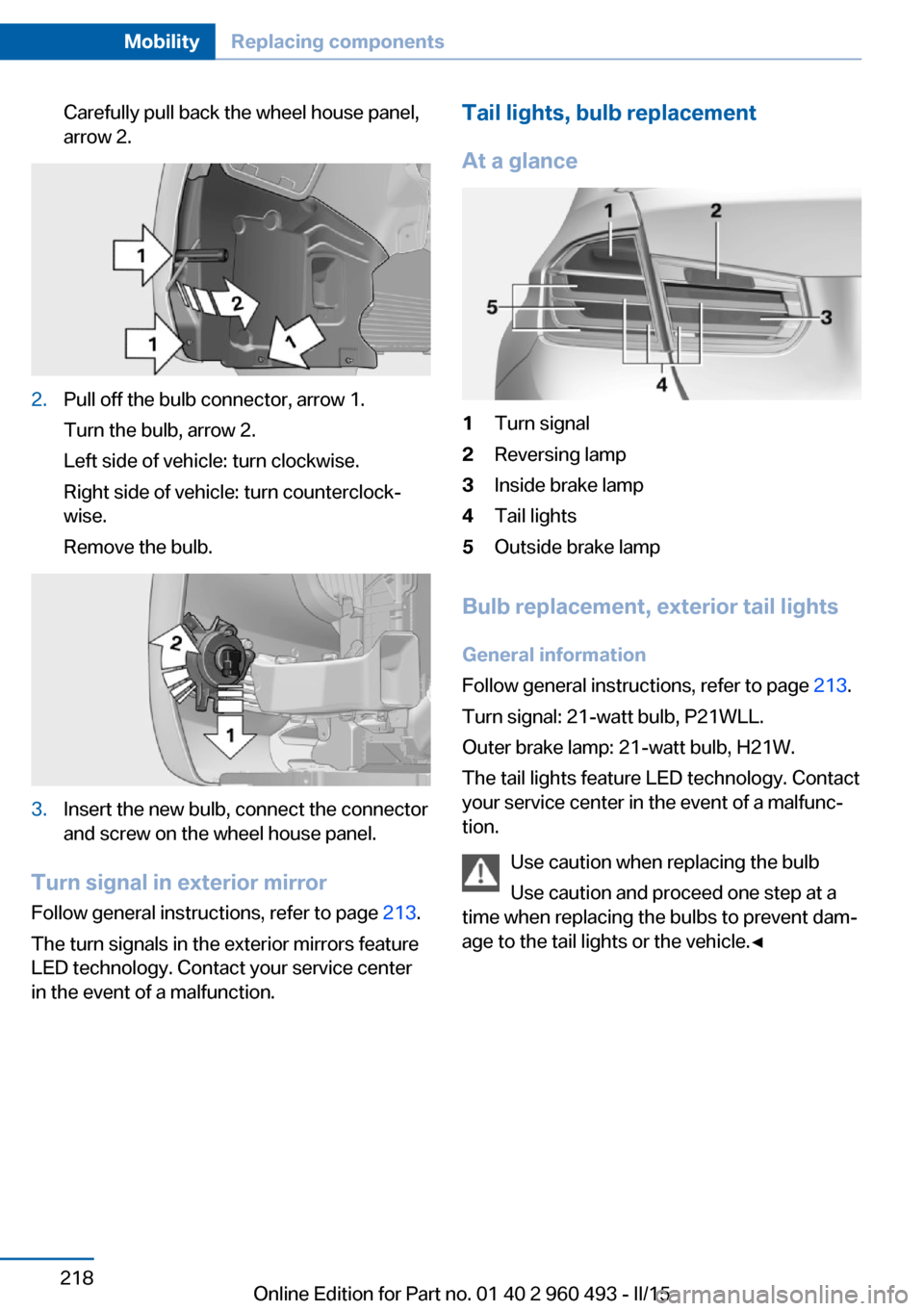
Carefully pull back the wheel house panel,
arrow 2.2.Pull off the bulb connector, arrow 1.
Turn the bulb, arrow 2.
Left side of vehicle: turn clockwise.
Right side of vehicle: turn counterclock‐
wise.
Remove the bulb.3.Insert the new bulb, connect the connector
and screw on the wheel house panel.
Turn signal in exterior mirror
Follow general instructions, refer to page 213.
The turn signals in the exterior mirrors feature
LED technology. Contact your service center
in the event of a malfunction.
Tail lights, bulb replacement
At a glance1Turn signal2Reversing lamp3Inside brake lamp4Tail lights5Outside brake lamp
Bulb replacement, exterior tail lights General information
Follow general instructions, refer to page 213.
Turn signal: 21-watt bulb, P21WLL.
Outer brake lamp: 21-watt bulb, H21W.
The tail lights feature LED technology. Contact
your service center in the event of a malfunc‐
tion.
Use caution when replacing the bulb
Use caution and proceed one step at a
time when replacing the bulbs to prevent dam‐
age to the tail lights or the vehicle.◀
Seite 218MobilityReplacing components218
Online Edition for Part no. 01 40 2 960 493 - II/15
Page 251 of 255

Safety belt reminder for driv‐er's seat and front passen‐
ger seat 55
Safety belts 54
Safety belts, care 233
Safety switch, windows 48
Safety systems, airbags 98
Saving fuel 176
Screen, refer to Control Dis‐ play 18
Screwdriver, see Onboard ve‐ hicle tool kit 212
Screw thread, see screw thread for tow fitting, screw
thread for tow fitting 229
Sealant 199
Seat and mirror memory 57
Seat belts, refer to Safety belts 54
Seat heating, front 54
Seat heating, rear 54
Seating position for chil‐ dren 61
Seats 51
Selection list in instrument cluster 87
Selector lever, Steptronic transmission 74
Sensors, care 233
Service and warranty 8
Service requirements, Condi‐ tion Based Service
CBS 210
Service requirements, dis‐ play 84
Services, ConnectedDrive
Servotronic 124
SET button, see Active Cruise Control, ACC 125
SET button, see Cruise con‐ trol 131
Settings, locking/unlock‐ ing 45
Settings on Control Dis‐ play 90 Settings, storing for seat, mir‐
ror 57
Shift paddles on the steering wheel 76
Side airbags 98
Side View 138
Signaling, horn 14
Signals when unlocking 45
Sitting safely 51
Size 236
Slide/tilt glass roof 48
Smallest turning radius 236
Snow chains 203
Socket 157
Socket, OBD Onboard Diag‐ nostics 211
Soot particulate filter 171
SOS button 224
Spare fuse 222
Specified engine oil types 208
Speed, average 88
Speed limit detection, on- board computer 89
Speed limiter, display 86
Speed Limit Information 86
Speed warning 89
Split screen 23
SPORT+ - program, Dynamic Driving Control 123
Sport displays, torque dis‐ play, performance dis‐
play 89
SPORT program, Dynamic Driving Control 123
Sport program, transmis‐ sion 75
Sport steering, variable 122
Stability control systems 120
Start/stop, automatic func‐ tion 67
Start/Stop button 65
Start function during malfunc‐ tion 35
Starting the engine 66 Status control display,
tires 102
Status information, iDrive 23
Status of Owner's Manual 7
Steering assistance 124
Steering wheel, adjusting 60
Steering wheel heating 60
Steptronic Sport transmis‐ sion, refer to Steptronic
transmission 73
Steptronic transmission 73
Stopping the engine 67
Storage compartment in the rear 165
Storage compartments 163
Storage compartments, loca‐ tions 163
Storage, tires 199
Storing the vehicle 233
Suitable engine oils 208
Summer tires, tread 197
Sun visor 157
Supplementary text mes‐ sage 82
Surround View 136
Switch for Dynamic Driv‐ ing 122
Switch-on times, parked-car ventilation 152
Switch, refer to Cockpit 14
Symbols 6
Symbols in the status field 23
T Tachometer 82
Tailgate, automatic 40
Tailgate, closing with no- touch activation 43
Tailgate, opening with no- touch activation 43
Tailgate via remote con‐ trol 38
Tail lights 218
Technical changes, refer to Safety 7 Seite 247Everything from A to ZReference247
Online Edition for Part no. 01 40 2 960 493 - II/15