2016.75 VAUXHALL ASTRA J brake light
[x] Cancel search: brake lightPage 208 of 291

206Driving and operatingDriving characteristics andtowing tips
Before attaching a trailer, lubricate the coupling ball. However, do not do
so if a stabiliser, which acts on the coupling ball, is being used to reduce snaking movements.
During trailer towing do not exceed a
speed of 50 mph. A maximum speed
of 60 mph is only appropriate if an
oscillation damper is used and the
permissible gross trailer weight does
not exceed the vehicle's curb weight.
For trailers with low driving stability
and caravan trailers, the use of an
oscillation damper is strongly
recommended.
If the trailer starts snaking, drive more slowly, do not attempt to correct the
steering and brake sharply if
necessary.
When driving downhill, drive in the
same gear as if driving uphill and
drive at a similar speed.
Adjust tyre pressure to the value
specified for full load 3 276.Trailer towing
Trailer loads9 Warning
Vehicles with engine B14XFT and
automatic transmission:
Use of towing equipment is
permissible for attaching
compatible bicycle carriers only.
Do not use towing equipment for
trailer towing.
The permissible trailer loads are
vehicle and engine-dependent
maximum values which must not be
exceeded. The actual trailer load is
the difference between the actual
gross weight of the trailer and the
actual coupling socket load with the
trailer coupled.
The permissible trailer loads are
specified in the vehicle documents. In
general, they are valid for gradients
up to max. 12%.
The permitted trailer load applies up to the specified incline and up to an
altitude of 1000 metres above sea
level. Since engine power decreases
as altitude increases due to the air
becoming thinner, therefore reducing
climbing ability, the permissible gross train weight also decreases by 10%
for every 1000 metres of additional
altitude. The gross train weight does
not have to be reduced when driving
on roads with slight inclines (less than
8%, e.g. motorways).
The permissible gross train weight
must not be exceeded. This weight is
specified on the identification plate
3 263.
Vertical coupling load
The vertical coupling load is the load
exerted by the trailer on the coupling
ball. It can be varied by changing the
weight distribution when loading the
trailer.
The maximum permissible vertical
coupling load (75 kg) is specified on
the towing equipment identification
plate and in the vehicle documents.
Always aim for the maximum load,
especially in the case of heavy
trailers. The vertical coupling load
should never fall below 25 kg.
Page 213 of 291

Vehicle care211Vehicle careGeneral Information...................211
Accessories and vehicle modifications .......................... 211
Vehicle storage ........................212
End-of-life vehicle recovery .....212
Vehicle checks ........................... 213
Performing work ......................213
Bonnet ..................................... 213
Engine oil ................................. 214
Engine coolant ......................... 215
Washer fluid ............................ 216
Brakes ..................................... 216
Brake fluid ............................... 216
Vehicle battery ......................... 217
Diesel fuel system bleeding .....218
Wiper blade replacement ........219
Bulb replacement .......................219
Halogen headlights ..................219
Fog lights ................................. 221
Tail lights ................................. 222
Side turn signal lights ..............228
Number plate light ...................229
Interior lights ............................ 229
Instrument panel illumination ...229Electrical system ........................230
Fuses ....................................... 230
Engine compartment fuse box . 231
Instrument panel fuse box .......233
Load compartment fuse box ....235
Vehicle tools .............................. 236
Tools ........................................ 236
Wheels and tyres .......................238
Winter tyres ............................. 238
Tyre designations ....................238
Tyre pressure .......................... 238
Tyre pressure monitoring system .................................... 239
Tread depth ............................. 243
Changing tyre and wheel size . 244 Wheel covers ........................... 244
Tyre chains .............................. 244
Tyre repair kit .......................... 245
Wheel changing .......................248
Spare wheel ............................ 250
Jump starting ............................. 253
Towing ....................................... 255
Towing the vehicle ...................255
Towing another vehicle ...........256
Appearance care .......................257
Exterior care ............................ 257
Interior care ............................. 258General Information
Accessories and vehiclemodifications
We recommend the use of genuine
parts and accessories and factory
approved parts specific for your
vehicle type. We cannot assess or guarantee reliability of other products
- even if they have a regulatory or
otherwise granted approval.
Do not make any modifications to the
electrical system, e.g. changes of
electronic control units (chip tuning).Caution
When transporting the vehicle on
a train or on a recovery vehicle, the
mud flaps might be damaged.
Page 225 of 291

Vehicle care223
4. Carefully withdraw tail lightassembly from recess and
remove.
5. Detach the cable from the retainer.
6.Press the three retaining lugs and
remove the bulb carrier from the
light assembly.
7. Remove and replace the bulbs:
Turn signal light ( 1)
Tail light/brake light ( 2)
On version with LED tail lights and
LED brake lights, only turn signal
light bulb ( 1) can be removed and
replaced.
8. Attach the bulb carrier to the light assembly.
9. Attach the cable to the retainer.
10. Attach the light assembly to the vehicle body and tighten the
securing nut from the inside of the load compartment. Attach cover.
Depending on the version, tail lights
and brake lights are designed as
LEDs. In case of failure, have LEDs replaced by a workshop.
Page 228 of 291

226Vehicle care2. Unscrew both plastic securingnuts from the inside by hand.
3. Carefully withdraw tail light assembly from recess and
remove.
4. Detach the cable from the retainer.
5. Release the retaining lugs and remove the bulb carrier from the
light assembly.
6. Remove and replace the bulbs:
Tail light/brake light ( 1)
Turn signal light ( 2)
7. Insert the bulb carrier into the light
assembly.
8. On version with LED tail lights and
brake lights, only turn signal light
bulb can be replaced: remove
bulb holder in the light assembly
by turning. Replace bulb in the
bulb holder.
9. Attach the cable to the retainer.
10. Attach the light assembly to the vehicle body and tighten the
securing nuts from the inside of
the load compartment. Attach
cover.
Page 229 of 291

Vehicle care227Depending on the version, tail lights
and brake lights are designed as
LEDs. In case of failure, have LEDs
replaced by a workshop.
Light assembly in the tailgate
1. Release the cover in the tailgate and remove it.
2. Unscrew the plastic securing nutby hand.
3. Carefully withdraw the lightassembly from the recesses and
remove.
4. Press the three retaining lugs and
remove the bulb carrier from the
light assembly.
Page 243 of 291

Vehicle care241After inflating, some driving may be
required to update the tyre pressure
values in the Driver Information
Centre. During this time w may
illuminate.
If w illuminates at lower temperatures
and extinguishes after driving, this
could be an indicator for approaching
a low tyre pressure condition. Check
tyre pressure.
Vehicle messages 3 120.
If the tyre pressure must be reduced
or increased, switch off ignition.
Only mount wheels with pressure
sensors, otherwise the tyre pressure
will not be displayed and w
illuminates continuously.
A spare wheel or temporary spare
wheel is not equipped with pressure
sensors. The tyre pressure
monitoring system is not operational
for these tyres. Control indicator w
illuminates. For the further three
tyres, the system remains
operational.The use of commercially-available
liquid tyre repair kits can impair the
function of the system. Factory-
approved repair kits can be used.
Operating electronic devices or being close to facilities using similar wave
frequencies could disrupt the tyre
pressure monitoring system.
Each time the tyres are replaced, tyre pressure monitoring system sensors
must be dismounted and serviced.
For the screwed sensor, replace
valve core and sealing ring. For the
clipped sensor, replace complete
valve stem.
Vehicle loading status Adjust tyre pressure to load condition
according to the tyre information label or tyre pressure chart 3 276, and
select the appropriate setting in the Tyre load menu in the Driver
Information Centre 3 113. This
setting is the reference for the tyre
pressure warnings.The Tyre load menu only appears if
the vehicle is in a standstill and the
parking brake is applied. On vehicles
with automatic transmission the
selector lever has to be in P.
Midlevel display:
Select the Tyre load page under the
Vehicle Information Menu ? in the
Driver Information Centre 3 113.
Select ● Light for comfort pressure up to
three people.
● Eco for Eco pressure up to three
people.
● Max for full loading.
Page 244 of 291
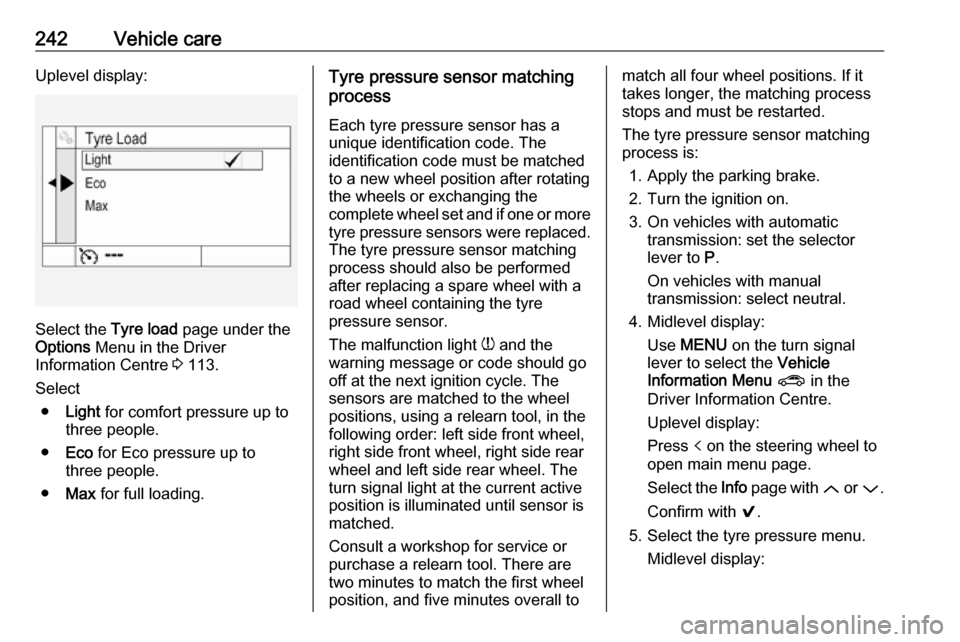
242Vehicle careUplevel display:
Select the Tyre load page under the
Options Menu in the Driver
Information Centre 3 113.
Select ● Light for comfort pressure up to
three people.
● Eco for Eco pressure up to
three people.
● Max for full loading.
Tyre pressure sensor matching
process
Each tyre pressure sensor has a
unique identification code. The
identification code must be matched
to a new wheel position after rotating the wheels or exchanging the
complete wheel set and if one or more tyre pressure sensors were replaced.
The tyre pressure sensor matching
process should also be performed
after replacing a spare wheel with a
road wheel containing the tyre
pressure sensor.
The malfunction light w and the
warning message or code should go
off at the next ignition cycle. The
sensors are matched to the wheel
positions, using a relearn tool, in the following order: left side front wheel,
right side front wheel, right side rear
wheel and left side rear wheel. The
turn signal light at the current active
position is illuminated until sensor is
matched.
Consult a workshop for service or
purchase a relearn tool. There are
two minutes to match the first wheel
position, and five minutes overall tomatch all four wheel positions. If it
takes longer, the matching process stops and must be restarted.
The tyre pressure sensor matching
process is:
1. Apply the parking brake.
2. Turn the ignition on.
3. On vehicles with automatic transmission: set the selector
lever to P.
On vehicles with manual
transmission: select neutral.
4. Midlevel display: Use MENU on the turn signal
lever to select the Vehicle
Information Menu ? in the
Driver Information Centre.
Uplevel display:
Press p on the steering wheel to
open main menu page.
Select the Info page with Q or P.
Confirm with 9.
5. Select the tyre pressure menu. Midlevel display:
Page 256 of 291

254Vehicle care● Do not lean over the vehiclebattery during jump starting.
● Do not allow the terminals of one
lead to touch those of the other
lead.
● The vehicles must not come into contact with each other during
the jump starting process.
● Apply the parking brake, transmission in neutral,
automatic transmission in P.
● Open the positive terminal protection cap of your vehicle in
the engine compartment and of
the booster vehicle battery.Lead connection order:
1. Connect the red lead to the positive terminal of the booster
vehicle battery.
2. Connect the other end of the red lead to the positive terminal of
your vehicle near the fuse box in
the engine compartment.
3. Connect the black lead to the negative terminal of the booster
vehicle battery.
4. Connect the other end of the black
lead to a vehicle grounding point
of your vehicle in the engine
compartment.
Route the leads so that they cannot
catch on rotating parts in the engine
compartment.
To start the engine: 1. Start the engine of the vehicle providing the jump.
2. After five minutes, start the other engine. Start attempts should be
made for no longer than
15 seconds at an interval of one
minute.3. Allow both engines to idle for approx. three minutes with the
leads connected.
4. Switch on electrical consumers (e.g. headlights, heated rear
window) of the vehicle receiving
the jump start.
5. Reverse above sequence exactly when removing leads.