Page 82 of 360
CABLE ROUTING DIAGRAM
2-39
Page 83 of 360
CABLE ROUTING DIAGRAM
2-40
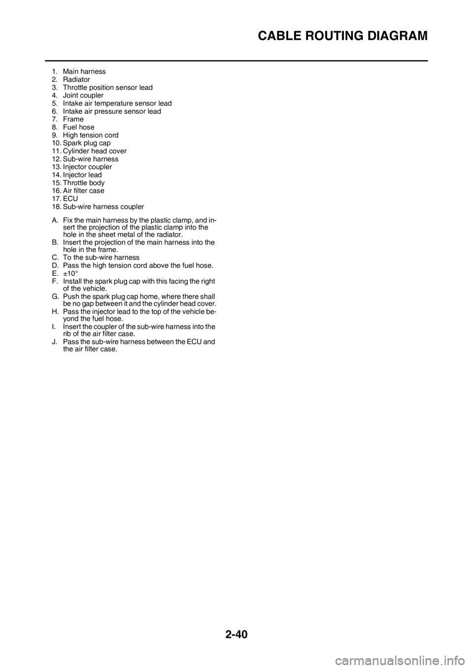
1. Main harness
2. Radiator
3. Throttle position sensor lead
4. Joint coupler
5. Intake air temperature sensor lead
6. Intake air pressure sensor lead
7. Frame
8. Fuel hose
9. High tension cord
10. Spark plug cap
11. Cylinder head cover
12. Sub-wire harness
13. Injector coupler
14. Injector lead
15. Throttle body
16. Air filter case
17. ECU
18. Sub-wire harness coupler
A. Fix the main harness by the plastic clamp, and in-
sert the projection of the plastic clamp into the
hole in the sheet metal of the radiator.
B. Insert the projection of the main harness into the
hole in the frame.
C. To the sub-wire harness
D. Pass the high tension cord above the fuel hose.
E. ±10°
F. Install the spark plug cap with this facing the right
of the vehicle.
G. Push the spark plug cap home, where there shall
be no gap between it and the cylinder head cover.
H. Pass the injector lead to the top of the vehicle be-
yond the fuel hose.
I. Insert the coupler of the sub-wire harness into the
rib of the air filter case.
J. Pass the sub-wire harness between the ECU and
the air filter case.
Page 84 of 360
CABLE ROUTING DIAGRAM
2-41
Page 85 of 360
CABLE ROUTING DIAGRAM
2-42
1. Brake master cylinder
2. Brake hose holder
3. Brake hoses
A. While installing the brake hose, direct a bend in
its pipe portion as shown, and bring it into contact
with the projection on the brake caliper.
B. Pass the brake hose into the brake hose holders.
C. If the brake hose interferes with the rear shock
absorber, correct its twist.
D. While installing the brake hose, direct a bend in
its pipe portion as shown, and bring it into contact
with the projection on the brake master cylinder.
Page 86 of 360
CABLE ROUTING DIAGRAM
2-43
Page 256 of 360
AC MAGNETO
5-61
2. Install:
• Woodruff key “1”
• Rotor “2”
TIP
• Clean the contact surfaces of the tapered por-
tions of the crankshaft and rotor.
• When installing the woodruff key, make sure
that its flat surface “a” is in parallel with the
crankshaft center line “b”.
• When installing the rotor, align the keyway “c”
of the rotor with the woodruff key.
3. Install:
• Washers
• Nut (rotor) “1”
4. Install:
• Dowel pin “1”
• Gasket (left crankcase cover) “2”
• Left crankcase cover “3”
• Lead holder “4”
• Bolt (left crankcase cover) “5”
TIP
Tighten the bolts in stages and in a crisscross
pattern.5. Connect:
• AC magneto lead
Refer to “CABLE ROUTING DIAGRAM” on
page 2-33.
Nut (rotor)
65 Nm (6.5 m·kgf, 47 ft·lbf)
Bolt (left crankcase cover)
10 Nm (1.0 m·kgf, 7.2 ft·lbf)
b11
c
2 a
T R..
1
New
T R..
1
1
2
3
5
5
5
5
4
45
Page 289 of 360

8
ELECTRICAL SYSTEM
IGNITION SYSTEM.......................................................................................... 8-2
CIRCUIT DIAGRAM ................................................................................... 8-2
TROUBLESHOOTING ............................................................................... 8-4
CHARGING SYSTEM....................................................................................... 8-6
CIRCUIT DIAGRAM ................................................................................... 8-6
TROUBLESHOOTING ............................................................................... 8-8
FUEL INJECTION SYSTEM........................................................................... 8-10
CIRCUIT DIAGRAM ................................................................................. 8-10
YAMAHA DIAGNOSTIC TOOL ................................................................ 8-12
TROUBLESHOOTING DETAILS ............................................................. 8-13
FUEL PUMP SYSTEM.................................................................................... 8-32
CIRCUIT DIAGRAM ................................................................................. 8-32
TROUBLESHOOTING ............................................................................. 8-34
ELECTRICAL COMPONENTS....................................................................... 8-36
CHECKING THE SWITCHES .................................................................. 8-38
CHECKING THE IGNITION SPARK GAP................................................ 8-41
CHECKING THE SPARK PLUG CAP ...................................................... 8-41
CHECKING THE IGNITION COIL ............................................................ 8-41
CHECKING THE CRANKSHAFT POSITION SENSOR........................... 8-42
CHECKING THE ECU .............................................................................. 8-43
CHECKING THE STATOR COIL ............................................................. 8-43
CHECKING THE RECTIFIER/REGULATOR ........................................... 8-43
CHECKING THE COOLANT TEMPERATURE SENSOR........................ 8-44
CHECKING THE THROTTLE POSITION SENSOR ................................ 8-44
CHECKING THE THROTTLE POSITION SENSOR
INPUT VOLTAGE .................................................................................... 8-45
CHECKING THE INTAKE AIR PRESSURE SENSOR ............................ 8-46
CHECKING THE INTAKE AIR TEMPERATURE SENSOR ..................... 8-46
CHECKING THE NEUTRAL SWITCH ..................................................... 8-46
CHECKING THE FUEL INJECTOR ......................................................... 8-47
Page 292 of 360
IGNITION SYSTEM
8-2
EAS1SL5321
IGNITION SYSTEM
EAS1SL5322CIRCUIT DIAGRAM
B/L Gy
BR
A
A
AA
B
RR R R R R R
B
B
B RR
R
Lg
LgB/WB/Y
B/YB
B
BP
PP
Sb
B/LP/B
P/B
YL
YL
L
G/WBr/W
G/WBr/W
B/LB/L
B/L
B/L
B/R
B/R
R/B
R/B
O
OROR
OR
R
R
SbB
GyR
B/W P L B/L
B/L GyB/L B/L B/L B/L B/L LL PP BBBB
PP
Sb
RB
B/RR
R B
B/Y PSb
BB
RR/B
LYB/L
B/W RLg
B/LBr/W
B/L P/B LB/LG/W
BB/Y BB/L B/L B/L B/L B/L B/LBBBBRR
PPPL L LRR RR R
B
OP Gy
R
B/Y Sb
P/B
R/BLgB/RG/WBr/WB/L L Y
RB
B/LGy
R
O
O
R(BLACK) (BLACK)
B/W
4
1
3
2
5
67
8
10
9
1211
13
1415
16
17


