2015 YAMAHA WR 250F ABS
[x] Cancel search: ABSPage 152 of 430

CHASSIS
4-5
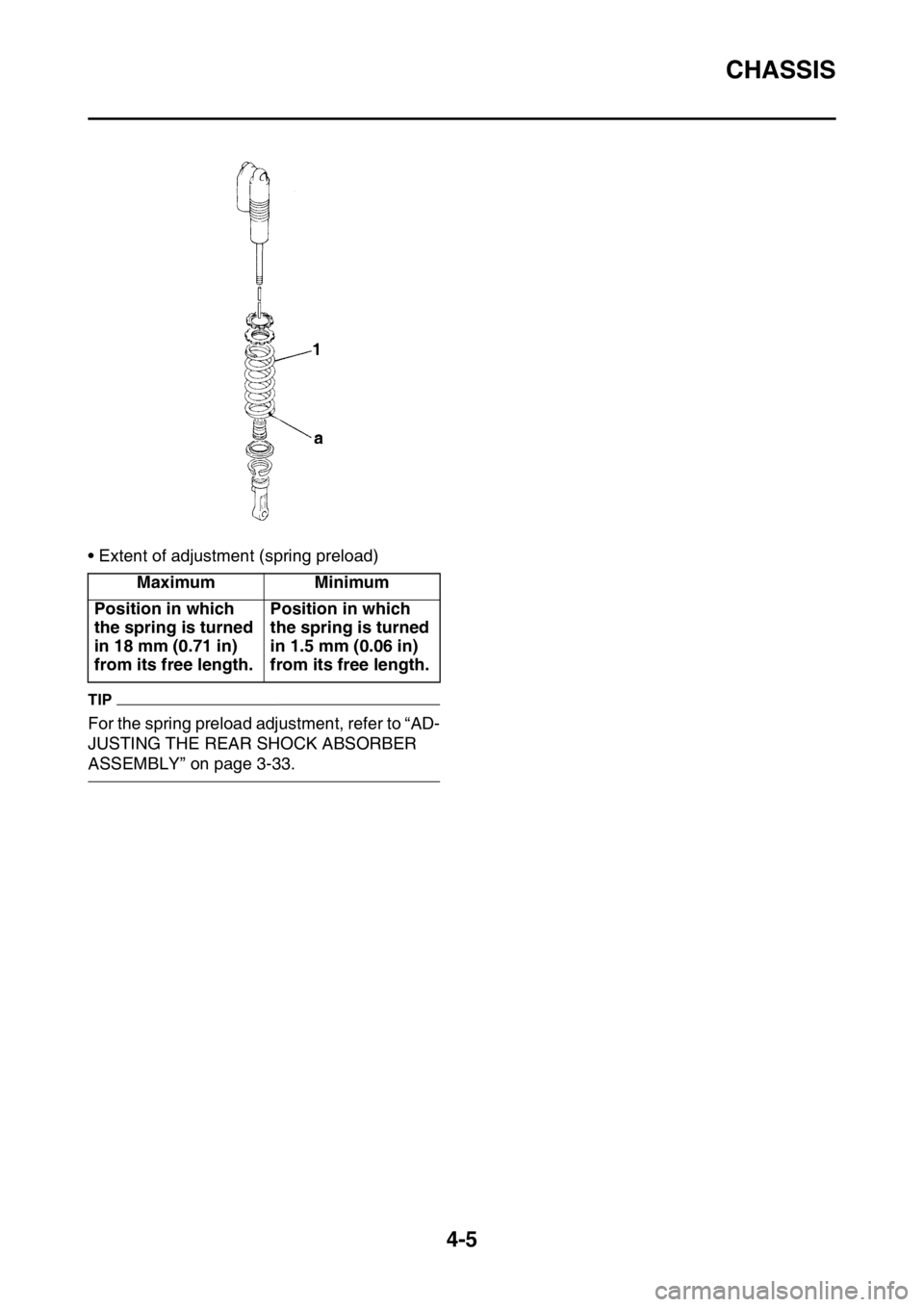
• Extent of adjustment (spring preload)
TIP
For the spring preload adjustment, refer to “AD-
JUSTING THE REAR SHOCK ABSORBER
ASSEMBLY” on page 3-33.Maximum Minimum
Position in which
the spring is turned
in 18 mm (0.71 in)
from its free length.Position in which
the spring is turned
in 1.5 mm (0.06 in)
from its free length.
Page 153 of 430

CHASSIS
4-6
EAS2GB2150SUSPENSION SETTING (FRONT FORK)
TIP
• If any of the following symptoms is experienced with the standard position as the base, make reset-
ting by reference to the adjustment procedure given in the same chart.
• Before any change, set the rear shock absorber sunken length to the standard figure 90–100 mm
(3.5–3.9 in).
SymptomSection
Check Adjust
JumpLarge
gapMedi-
um
gapSmall
gap
Stiff over entire
rangeCompression
damping forceTurn adjuster counterclock-
wise (about 2 clicks) to de-
crease damping.
Oil amount Decrease oil amount by about
5–10 cm
3 (0.2–0.3 US oz, 0.2–
0.4 Imp.oz).
Spring Replace with soft spring.
Unsmooth
movement over
entire rangeOuter tube
Inner tubeCheck for any bends, dents,
other noticeable scars, etc. If
any, replace affected parts.
Slide metal Replace with a new one for ex-
tended use.
Piston metal Replace with a new one for ex-
tended use.
Lower bracket
tightening
torqueRetighten to specified torque.
Poor initial
movementRebound
damping forceTurn adjuster counterclock-
wise (about 2 clicks) to de-
crease damping.
Oil seals Apply grease in oil seal wall.
Soft over entire
range, bottom-
ing outCompression
damping forceTurn adjuster clockwise (about
2 clicks) to increase damping.
Oil amount Increase oil amount by about
5–10 cm
3 (0.2–0.3 US oz, 0.2–
0.4 Imp.oz).
Spring Replace with stiff spring.
Stiff toward
stroke endOil amountDecrease oil amount by about
5 cm
3 (0.2 US oz, 0.2 Imp.oz).
Soft toward
stroke end, bot-
toming outOil amountIncrease oil amount by about 5
cm
3 (0.2 US oz, 0.2 Imp.oz).
Stiff initial
movementCompression
damping forceTurn adjuster counterclock-
wise (about 2 clicks) to de-
crease damping.
Page 154 of 430

CHASSIS
4-7
EAS2GB2151SUSPENSION SETTING (REAR SHOCK ABSORBER)
TIP
• If any of the following symptoms is experienced with the standard position as the base, make reset-
ting by reference to the adjustment procedure given in the same chart.
• Adjust the rebound damping in 2-click increments or decrements.
• Adjust the low compression damping in 1-click increments or decrements.
• Adjust the high compression damping in 1/6 turn increments or decrements. Low front, tend-
ing to lower
front postureCompression
damping forceTurn adjuster clockwise (about
2 clicks) to increase damping.
Rebound
damping forceTurn adjuster counterclock-
wise (about 2 clicks) to de-
crease damping.
Balance with
rear endSet sunken length for 95–100
mm (3.7–3.9 in) when one
passenger is astride seat (low-
er rear posture).
Oil amount Increase oil amount by about 5
cm
3 (0.2 US oz, 0.2 Imp.oz).
“Obtrusive”
front, tending to
upper front pos-
tureCompression
damping forceTurn adjuster counterclock-
wise (about 2 clicks) to de-
crease damping.
Balance with
rear endSet sunken length for 90–95
mm (3.5–3.7 in) when one
passenger is astride seat (up-
per rear posture).
Spring Replace with soft spring.
Oil amount Decrease oil amount by about
5–10 cm
3 (0.2–0.3 US oz, 0.2–
0.4 Imp.oz).
SymptomSection
Check Adjust
JumpLarge
gapMedi-
um
gapSmall
gap
Stiff, tending to
sinkRebound
damping forceTurn adjuster counterclock-
wise (about 2 clicks) to de-
crease damping.
Spring set
lengthSet sunken length for 90–100
mm (3.5–3.9 in) when one
passenger is astride seat.
Spongy and un-
stableRebound
damping forceTurn adjuster clockwise (about
2 clicks) to increase damping.
Low compres-
sion dampingTurn adjuster clockwise (about
1 click) to increase damping.
Spring Replace with stiff spring. SymptomSection
Check Adjust
JumpLarge
gapMedi-
um
gapSmall
gap
Page 158 of 430

HANDLEBAR................................................................................................. 5-33
REMOVING THE HANDLEBAR............................................................... 5-35
CHECKING THE HANDLEBAR ............................................................... 5-35
INSTALLING THE HANDLEBAR ............................................................. 5-35
FRONT FORK................................................................................................. 5-40
REMOVING THE FRONT FORK LEGS ................................................... 5-42
DISASSEMBLING THE FRONT FORK LEGS ......................................... 5-42
CHECKING THE FRONT FORK LEGS ................................................... 5-43
ASSEMBLING THE FRONT FORK LEGS ............................................... 5-44
INSTALLING THE FRONT FORK LEGS ................................................. 5-50
STEERING HEAD........................................................................................... 5-53
REMOVING THE LOWER BRACKET...................................................... 5-54
CHECKING THE STEERING HEAD ........................................................ 5-54
INSTALLING THE STEERING HEAD ...................................................... 5-54
REAR SHOCK ABSORBER ASSEMBLY..................................................... 5-57
HANDLING THE REAR SHOCK ABSORBER ......................................... 5-60
DISPOSING OF A REAR SHOCK ABSORBER ...................................... 5-60
REMOVING THE REAR SHOCK ABSORBER ASSEMBLY.................... 5-60
REMOVING THE BEARING..................................................................... 5-60
CHECKING THE REAR SHOCK ABSORBER ASSEMBLY .................... 5-61
CHECKING THE CONNECTING ARM AND RELAY ARM ...................... 5-61
INSTALLING THE RELAY ARM............................................................... 5-61
INSTALLING THE REAR SHOCK ABSORBER ASSEMBLY .................. 5-62
SWINGARM.................................................................................................... 5-64
REMOVING THE SWINGARM................................................................. 5-65
REMOVING THE BEARING..................................................................... 5-65
CHECKING THE SWINGARM ................................................................. 5-65
INSTALLING THE SWINGARM ............................................................... 5-66
CHAIN DRIVE................................................................................................. 5-67
REMOVING THE DRIVE CHAIN.............................................................. 5-68
CHECKING THE DRIVE CHAIN .............................................................. 5-68
CHECKING THE DRIVE SPROCKET...................................................... 5-69
CHECKING THE REAR WHEEL SPROCKET ......................................... 5-69
INSTALLING THE DRIVE CHAIN ............................................................ 5-69
Page 175 of 430

FRONT BRAKE
5-17
EAS2GB2170INTRODUCTIONEWA
WARNING
If you need to disassemble the disc brake
components, observe the following precau-
tions.
• Never disassemble the brake components
unless absolutely necessary.
• If there is any problem with connections
on the hydraulic brake system, perform
the following jobs.
Disassemble the brake system, drain the
brake fluid, and clean it. After that, add a
suitable amount of brake fluid. Then, bleed
it after reassembly.
• Use only brake fluid for washing brake
components.
• Use new brake fluid for cleaning the brake
components.
• Immediately wipe off the spilled brake fluid
to avoid damage to painted surfaces or
plastic parts.
• Handle brake fluid with special care not to
let it enter your eyes so that you may not
lost your eyesight.
• FIRST AID FOR BRAKE FLUID ENTERING
THE EYES:
• Flush with water for 15 minutes and get
immediate medical attention.
EAS2GB2171CHECKING THE FRONT BRAKE DISC
1. Remove:
• Front wheel
Refer to “FRONT WHEEL” on page 5-4.
2. Check:
• Front brake disc
Damage/galling Replace.
3. Measure:
• Brake disc thickness
Measure the brake disc thickness at a few
different locations.
Out of specification Replace.4. Install:
• Front wheel
Refer to “FRONT WHEEL” on page 5-4.
EAS2GB2172REMOVING THE FRONT BRAKE CALIPER
TIP
Before disassembling the brake caliper, drain
the brake fluid from the entire brake system.
1. Remove:
• Union bolt
• Copper washers
• Brake hose
TIP
Put the end of the brake hose into a container
and pump out the brake fluid.
EAS2GB2173DISASSEMBLING THE FRONT BRAKE CAL-
IPER
1. Remove:
• Brake caliper piston “1”
• Brake caliper piston dust seal “2”
• Brake caliper piston seals “3”
▼▼▼▼▼▼▼▼▼▼▼▼▼▼▼▼▼▼▼▼▼▼▼▼▼▼▼▼▼▼▼▼
a. Blow compressed air into the brake hose
joint opening to force out the piston from the
brake caliper.
EWA
WARNING
• Cover the brake caliper piston with a rag.
Be careful not to get injured when the pis-
ton is expelled from the brake caliper.
• Never try to pry out the brake caliper pis-
ton.
Brake disc thickness limit
2.5 mm (0.10 in)
3
2
1
Page 185 of 430

REAR BRAKE
5-27
EAS2GB2183INTRODUCTIONEWA
WARNING
If you need to disassemble the disc brake
components, observe the following precau-
tions.
• Never disassemble the brake components
unless absolutely necessary.
• If there is any problem with connections
on the hydraulic brake system, perform
the following jobs.
Disassemble the brake system, drain the
brake fluid, and clean it. After that, add a
suitable amount of brake fluid. Then, bleed
it after reassembly.
• Use only brake fluid for washing internal
brake components.
• Use new brake fluid for cleaning the brake
components.
• Immediately wipe off the spilled brake fluid
to avoid damage to painted surfaces or
plastic parts.
• Handle brake fluid with special care not to
let it enter your eyes so that you may not
lost your eyesight.
• FIRST AID FOR BRAKE FLUID ENTERING
THE EYES:
• Flush with water for 15 minutes and get
immediate medical attention.
EAS2GB2184CHECKING THE REAR BRAKE DISC
1. Remove:
• Rear wheel
Refer to “REAR WHEEL” on page 5-9.
2. Check:
• Brake disc
Damage/galling Replace.
3. Measure:
• Brake disc thickness
Measure the brake disc thickness at a few
different locations.
Out of specification Replace.
Refer to “CHECKING THE FRONT BRAKE
DISC” on page 5-17.
4. Measure:
• Brake disc deflection
Out of specification Correct the brake disc
deflection or replace the brake disc.5. Adjust:
• Brake disc deflection
▼▼▼▼▼▼▼▼▼▼▼▼▼▼▼▼▼▼▼▼▼▼▼▼▼▼▼▼▼▼▼▼
a. Remove the brake disc.
b. Turn the mounted position of the brake disc
by one bolt hole.
c. Install the brake disc.
TIP
Tighten the brake disc bolts in stages and in a
crisscross pattern.
d. Measure the brake disc deflection.
e. If out of specification, repeat the adjustment
steps until the brake disc deflection is within
specification.
f. If the brake disc deflection cannot be
brought within specification, replace the
brake disc.
▲▲▲▲▲▲▲▲▲▲▲▲▲▲▲▲▲▲▲▲▲▲▲▲▲▲▲▲▲▲▲▲
6. Install:
• Rear wheel
Refer to “REAR WHEEL” on page 5-9. Brake disc thickness limit
3.5 mm (0.14 in)
Brake disc deflection limit
0.15 mm (0.0059 in)
Brake disc bolt
14 Nm (1.4 m·kgf, 10 ft·lbf)
LOCTITE®
T R..
Page 215 of 430

REAR SHOCK ABSORBER ASSEMBLY
5-57
EAS2GB2209
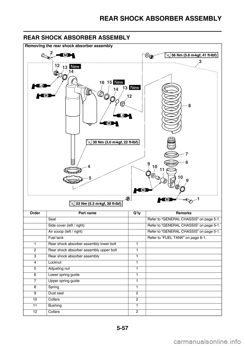
REAR SHOCK ABSORBER ASSEMBLY
Removing the rear shock absorber assembly
Order Part name Q’ty Remarks
Seat Refer to “GENERAL CHASSIS” on page 5-1.
Side cover (left / right) Refer to “GENERAL CHASSIS” on page 5-1.
Air scoop (left / right) Refer to “GENERAL CHASSIS” on page 5-1.
Fuel tank Refer to “FUEL TANK” on page 8-1.
1 Rear shock absorber assembly lower bolt 1
2 Rear shock absorber assembly upper bolt 1
3 Rear shock absorber assembly 1
4 Locknut 1
5 Adjusting nut 1
6 Lower spring guide 1
7 Upper spring guide 1
8Spring 1
9 Dust seal 2
10 Collars 2
11 Bushing 1
12 Collars 2
2
12
1615
1413
12
14
4
5
7
6
83
9
9 10
10 11
1
New
New
13New
LS
LS
M
M
M
M
M
Page 216 of 430

REAR SHOCK ABSORBER ASSEMBLY
5-58
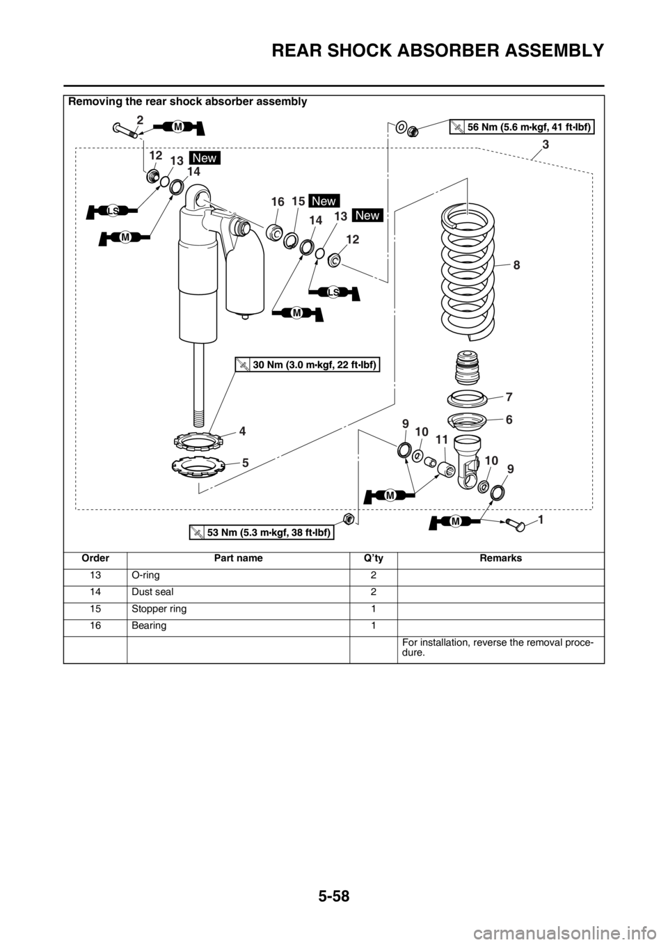
13 O-ring 2
14 Dust seal 2
15 Stopper ring 1
16 Bearing 1
For installation, reverse the removal proce-
dure.
Removing the rear shock absorber assembly
Order Part name Q’ty Remarks
2
12
1615
1413
12
14
4
5
7
6
83
9
9 10
10 11
1
New
New
13New
LS
LS
M
M
M
M
M