2015 YAMAHA WR 250F steering wheel
[x] Cancel search: steering wheelPage 140 of 430

CHASSIS
3-36
2. Tighten:
• Spokes
Use a spoke nipple wrench “1” for tighten-
ing.
TIP
• Do not give a half turn (180 °) or more for one
tightening.
• Make sure that tightening after a break-in is
done until the initial looseness in nipples dis-
appears.
• Make sure that tightening is done in stages,
not at a time.
EAS2GB2123CHECKING THE WHEELS
1. Check:
• Wheel(s)
Damage/out-of-round Replace.
EWA
WARNING
Never attempt to make any repairs to the
wheel.
TIP
After replacing a tire or a wheel, always bal-
ance the wheel.
EAS2GB2124CHECKING THE WHEEL BEARINGS
1. Check:
• Wheel bearings
Refer to “CHECKING THE FRONT WHEEL”
on page 5-5 and “CHECKING THE REAR
WHEEL” on page 5-10.
EAS2GB2125
CHECKING AND ADJUSTING THE STEER-
ING HEAD
1. Use a suitable stand to raise the front wheel
off the ground.
EWA
WARNING
Securely support the vehicle so that there is
no danger of it falling over.
2. Check:
• Steering head
Grasp the bottom of the front fork legs and
gently rock the front fork.
Blinding/looseness Adjust the steering
head.
3. Remove:
• Handlebar
Refer to “HANDLEBAR” on page 5-33.
• Upper bracket
Refer to “STEERING HEAD” on page 5-53.
4. Adjust:
• Steering head
▼▼▼▼▼▼▼▼▼▼▼▼▼▼▼▼▼▼▼▼▼▼▼▼▼▼▼▼▼▼▼▼
a. Remove the washer “1”.
b. After loosening the ring nut “2” with a steer-
ing nut wrench “3”, tighten it to the specified
torque.
TIP
• Set the torque wrench at a right angle to the
steering nut wrench.
• Move the steering to the left and right a couple
of times to check that it moves smoothly. Spoke nipple wrench (6–7)
90890-01521
Spoke nipple wrench (6–7)
YM-01521
Spokes
2.5 Nm (0.25 m·kgf, 1.8 ft·lbf)
1
T R..
1
3
2
Page 158 of 430

HANDLEBAR................................................................................................. 5-33
REMOVING THE HANDLEBAR............................................................... 5-35
CHECKING THE HANDLEBAR ............................................................... 5-35
INSTALLING THE HANDLEBAR ............................................................. 5-35
FRONT FORK................................................................................................. 5-40
REMOVING THE FRONT FORK LEGS ................................................... 5-42
DISASSEMBLING THE FRONT FORK LEGS ......................................... 5-42
CHECKING THE FRONT FORK LEGS ................................................... 5-43
ASSEMBLING THE FRONT FORK LEGS ............................................... 5-44
INSTALLING THE FRONT FORK LEGS ................................................. 5-50
STEERING HEAD........................................................................................... 5-53
REMOVING THE LOWER BRACKET...................................................... 5-54
CHECKING THE STEERING HEAD ........................................................ 5-54
INSTALLING THE STEERING HEAD ...................................................... 5-54
REAR SHOCK ABSORBER ASSEMBLY..................................................... 5-57
HANDLING THE REAR SHOCK ABSORBER ......................................... 5-60
DISPOSING OF A REAR SHOCK ABSORBER ...................................... 5-60
REMOVING THE REAR SHOCK ABSORBER ASSEMBLY.................... 5-60
REMOVING THE BEARING..................................................................... 5-60
CHECKING THE REAR SHOCK ABSORBER ASSEMBLY .................... 5-61
CHECKING THE CONNECTING ARM AND RELAY ARM ...................... 5-61
INSTALLING THE RELAY ARM............................................................... 5-61
INSTALLING THE REAR SHOCK ABSORBER ASSEMBLY .................. 5-62
SWINGARM.................................................................................................... 5-64
REMOVING THE SWINGARM................................................................. 5-65
REMOVING THE BEARING..................................................................... 5-65
CHECKING THE SWINGARM ................................................................. 5-65
INSTALLING THE SWINGARM ............................................................... 5-66
CHAIN DRIVE................................................................................................. 5-67
REMOVING THE DRIVE CHAIN.............................................................. 5-68
CHECKING THE DRIVE CHAIN .............................................................. 5-68
CHECKING THE DRIVE SPROCKET...................................................... 5-69
CHECKING THE REAR WHEEL SPROCKET ......................................... 5-69
INSTALLING THE DRIVE CHAIN ............................................................ 5-69
Page 211 of 430

STEERING HEAD
5-53
EAS2GB2205
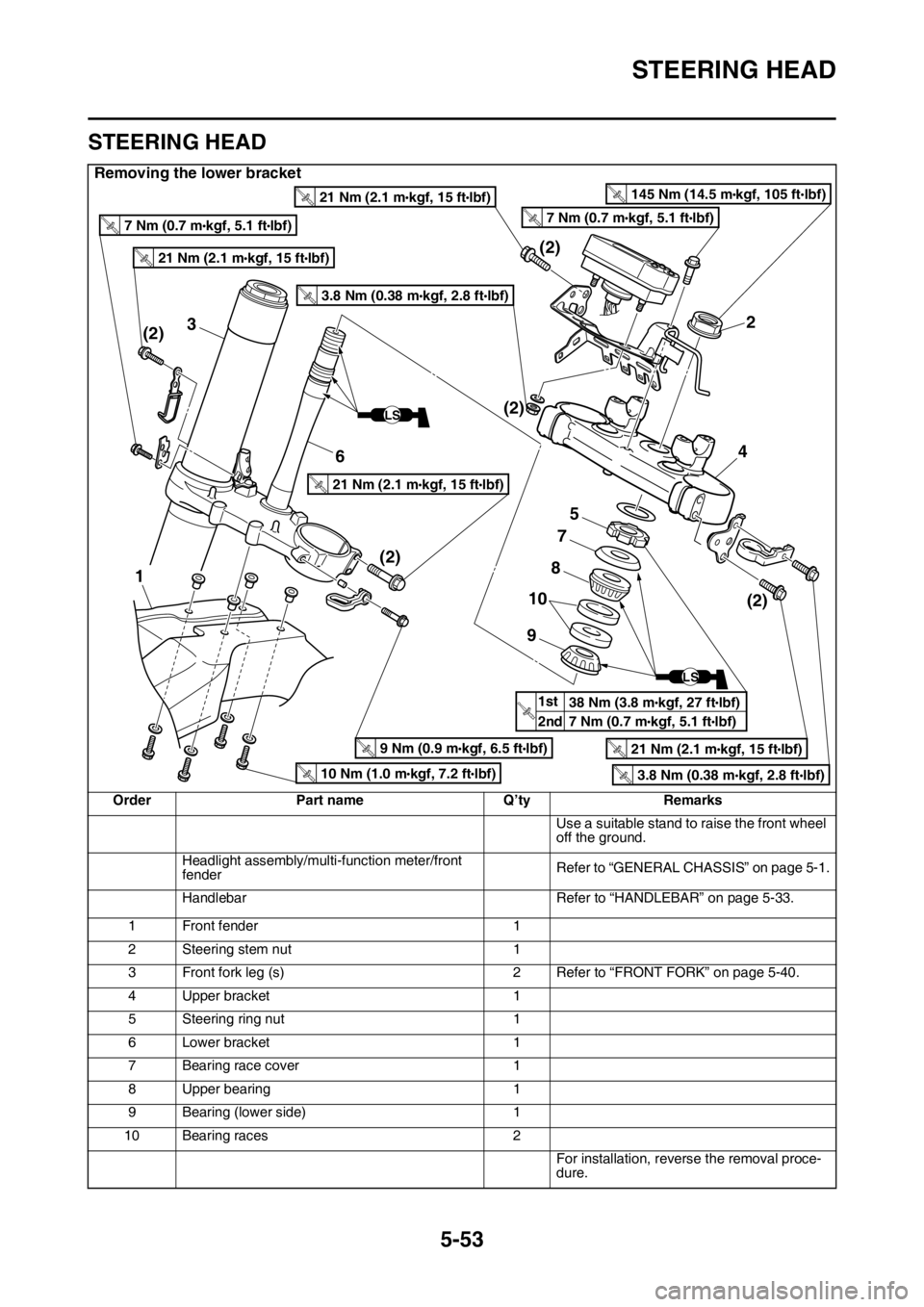
STEERING HEAD
Removing the lower bracket
Order Part name Q’ty Remarks
Use a suitable stand to raise the front wheel
off the ground.
Headlight assembly/multi-function meter/front
fenderRefer to “GENERAL CHASSIS” on page 5-1.
Handlebar Refer to “HANDLEBAR” on page 5-33.
1 Front fender 1
2 Steering stem nut 1
3 Front fork leg (s) 2 Refer to “FRONT FORK” on page 5-40.
4 Upper bracket 1
5 Steering ring nut 1
6 Lower bracket 1
7 Bearing race cover 1
8 Upper bearing 1
9 Bearing (lower side) 1
10 Bearing races 2
For installation, reverse the removal proce-
dure.
2
4
5
7
3
(2)(2)
(2)
(2) (2)
1
6
8
9
10
LS
1st
2ndT.R.
LS
T.R.21 Nm (2.1 mlbf) kgf, 15 ft
T.R.21 Nm (2.1 mlbf) kgf, 15 ft
T.R.21 Nm (2.1 mlbf) kgf, 15 ft
T.R.21 Nm (2.1 mlbf) kgf, 15 ft
T.R.3.8 Nm (0.38 mlbf) kgf, 2.8 ft
T.R.3.8 Nm (0.38 mlbf) kgf, 2.8 ft
T.R.9 Nm (0.9 mlbf) kgf, 6.5 ft
T.R.7 Nm (0.7 mlbf) kgf, 5.1 ftT.R.7 Nm (0.7 mlbf) kgf, 5.1 ft
T.R.10 Nm (1.0 mlbf) kgf, 7.2 ft
T.R.145 Nm (14.5 mlbf) kgf, 105 ft
38 Nm (3.8 m
lbf) kgf, 27 ft
7 Nm (0.7 m
lbf) kgf, 5.1 ft
Page 212 of 430

STEERING HEAD
5-54
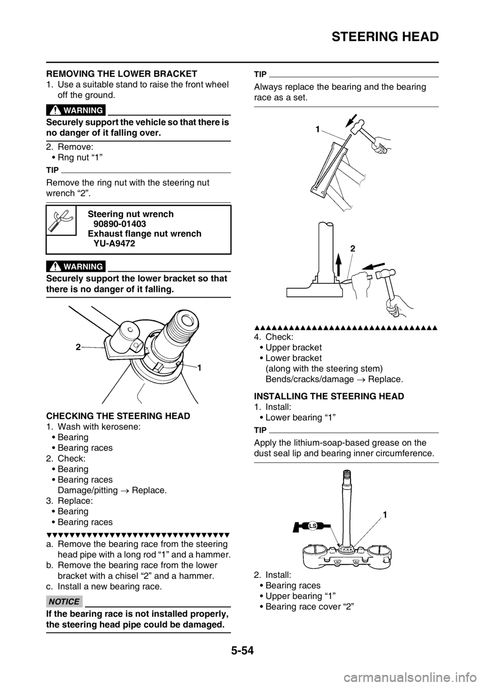
EAS2GB2206REMOVING THE LOWER BRACKET
1. Use a suitable stand to raise the front wheel
off the ground.
EWA
WARNING
Securely support the vehicle so that there is
no danger of it falling over.
2. Remove:
• Rng nut “1”
TIP
Remove the ring nut with the steering nut
wrench “2”.
EWA
WARNING
Securely support the lower bracket so that
there is no danger of it falling.
EAS2GB2207CHECKING THE STEERING HEAD
1. Wash with kerosene:
• Bearing
• Bearing races
2. Check:
• Bearing
• Bearing races
Damage/pitting Replace.
3. Replace:
• Bearing
• Bearing races
▼▼▼▼▼▼▼▼▼▼▼▼▼▼▼▼▼▼▼▼▼▼▼▼▼▼▼▼▼▼▼▼
a. Remove the bearing race from the steering
head pipe with a long rod “1” and a hammer.
b. Remove the bearing race from the lower
bracket with a chisel “2” and a hammer.
c. Install a new bearing race.
ECA
NOTICE
If the bearing race is not installed properly,
the steering head pipe could be damaged.
TIP
Always replace the bearing and the bearing
race as a set.
▲▲▲▲▲▲▲▲▲▲▲▲▲▲▲▲▲▲▲▲▲▲▲▲▲▲▲▲▲▲▲▲
4. Check:
• Upper bracket
• Lower bracket
(along with the steering stem)
Bends/cracks/damage Replace.
EAS2GB2208INSTALLING THE STEERING HEAD
1. Install:
• Lower bearing “1”
TIP
Apply the lithium-soap-based grease on the
dust seal lip and bearing inner circumference.
2. Install:
• Bearing races
• Upper bearing “1”
• Bearing race cover “2” Steering nut wrench
90890-01403
Exhaust flange nut wrench
YU-A9472
Page 420 of 430

TROUBLESHOOTING
10-3
Fuel system
1. Throttle body
• Damaged or loose throttle body joint
2. Air filter
• Clogged air filter element
Chassis
1. Brake(s)
• Dragging brake
Electrical system
1. Spark plug
• Incorrect spark plug gap
• Incorrect spark plug heat range
2. Ignition system
• Faulty ECU
• Faulty coolant temperature sensor
EAS2GB2418OVERCOOLING
Cooling system
1. Coolant temperature sensor
• Faulty coolant temperature sensor
EAS2GB2419POOR BRAKING PERFORMANCE
Chassis
1. Brake(s)
• Worn brake pad
• Worn brake disc
• Air in hydraulic brake system
• Leaking brake fluid
• Defective master cylinder kit
• Faulty brake caliper kit
• Faulty brake caliper seal
• Loose union bolt
• Damaged brake hose
• Oil or grease on the brake disc
• Oil or grease on the brake pad
• Incorrect brake fluid level
EAS2GB2420FRONT FORK OIL LEAKING
Chassis
1. Front fork
• Bent, damaged, or rusty inner tube
• Cracked or damaged outer tube
• Improperly installed oil seal
• Damaged oil seal lip
• Incorrect oil level (high)
• Loose damper rod assembly bolt
• Damaged damper rod assembly bolt copper
washer
• Cracked or damaged cap bolt O-ring
EAS2GB2421FAULTY FRONT FORK LEGS
Chassis
1. Front fork
• Bent or damaged inner tube
• Bent or damaged outer tube
• Broken fork spring
• Bent or damaged damper rod
• Incorrect oil viscosity
• Incorrect oil level
EAS2GB2422UNSTABLE HANDLING
Chassis
1. Handlebar
• Bent or improperly installed handlebar
2. Steering head components
• Improperly installed upper bracket
• Improperly installed lower bracket
(improperly tightened ring nut)
• Bent steering stem
• Damaged ball bearing or bearing race
3. Front fork leg (s)
• Uneven oil levels (both front fork legs)
• Unevenly tensioned fork spring (both front
fork legs)
• Broken fork spring
• Bent or damaged inner tube
• Bent or damaged outer tube
4. Swingarm
• Worn bearing or bushing
• Bent or damaged swingarm
5. Rear shock absorber assembly (-ies)
• Faulty rear shock absorber spring
• Leaking oil or gas
6. Tire (s)
• Uneven tire pressures (front and rear)
• Incorrect tire pressure
• Uneven tire wear
7. Wheel (s)
• Incorrect wheel balance
• Broken or loose spoke
• Damaged wheel bearing
• Bent or loose wheel axle
• Excessive wheel runout
8. Frame
• Bent frame
• Damaged steering head pipe
• Improperly installed bearing race