2015 YAMAHA PW50 lock
[x] Cancel search: lockPage 9 of 76

TABLE OF CONTENTS
LOCATION OF IMPORTANT
LABELS..............................................1-1
SAFETY INFORMATION ...................2-1
DESCRIPTION ...................................3-1
Left view ..........................................3-1
Right view ........................................3-2
Controls and instruments ................3-3
INSTRUMENT AND CONTROL
FUNCTIONS .......................................4-1
Handlebar switch ............................4-1
Speed limiter and power reduction plate .............................................4-1
Front brake lever .............................4-2
Rear brake lever ..............................4-3
Fuel tank cap ...................................4-3
Fuel ..................................................4-3
Fuel tank breather hose...................4-5
2-stroke engine oil ...........................4-6
Fuel cock .........................................4-6
Starter (choke) lever .......................4-7
Kickstarter .......................................4-7
Seat .................................................4-7
Cable lock (for Europe) ....................4-8 FOR YOUR SAFETY –
PRE-OPERATION CHECKS
............. 5-1
OPERATION AND IMPORTANT
RIDING POINTS ................................ 6-1
Starting and warming up a cold engine .......................................... 6-1
Starting a warm engine................... 6-1
Starting off ...................................... 6-2
Acceleration and deceleration ........ 6-2
Braking............................................ 6-2
Engine break-in............................... 6-3
Parking ............................................ 6-4
PERIODIC MAINTENANCE AND
ADJUSTMENT .................................. 7-1
Owner’s tool kit............................... 7-2
Periodic maintenance chart for the
emission control system ............. 7-3
General maintenance and
lubrication chart .......................... 7-4
Checking the spark plug................. 7-6
Removing the power reduction plate............................................. 7-7
Transmission oil .............................. 7-8
Middle and final gear cases ............ 7-9
Cleaning the air filter element ......... 7-9
Cleaning the spark arrester .......... 7-10
Adjusting the carburetor ............... 7-11
Adjusting the engine idling speed......................................... 7-11 Checking the throttle grip free
play ............................................ 7-12
Tires .............................................. 7-12
Panel wheels ................................. 7-14
Adjusting the front and rear brake lever free play ............................ 7-14
Checking the front and rear brake shoes ......................................... 7-15
Checking and lubricating the cables ........................................ 7-16
Checking and lubricating the
throttle grip and cable ............... 7-16
Adjusting the Autolube pump ....... 7-16
Lubricating the front and rear brake levers ............................... 7-17
Checking and lubricating the centerstand ................................ 7-17
Checking the front fork ................. 7-17
Checking the steering ................... 7-18
Checking the wheel bearings ........ 7-18
Front wheel ................................... 7-19
Rear wheel .................................... 7-20
Troubleshooting ............................ 7-23
Troubleshooting chart ................... 7-24
MOTORCYCLE CARE AND
STORAGE .......................................... 8-1
Matte color caution ......................... 8-1
Care................................................. 8-1
Storage............................................ 8-3
U2SA81E0.book Page 1 Monday, June 2, 2014 2:00 PM
Page 28 of 76

INSTRUMENT AND CONTROL FUNCTIONS
4-1
4
EAU40661
Handle bar switch
EAU40675
En gine stop switch
“OFF/RUN/START”
Set this switch to “START” before
starting the engine. Set this switch to
“RUN” after warming up the engine or
before starting off. Set this switch to
“OFF” to stop the engine.TIP The engine cannot be started with
this switch set to the “RUN” posi-
tion.
The engine speed is limited while
this switch is set to the “START”
position, therefore the motorcycle
cannot be ridden in that switch
position.
EAU41045
Speed limiter an d power re-
d uction plateYour motorcycle is equipped with an
adjustable speed limiter and a power
reduction plate. The speed limiter
keeps the throttle from fully opening,
even when the throttle grip is turned to
the maximum. The power reduction
plate is installed in the exhaust mani-
fold to limit the amount of power avail-
able while learning.
Speed limiter
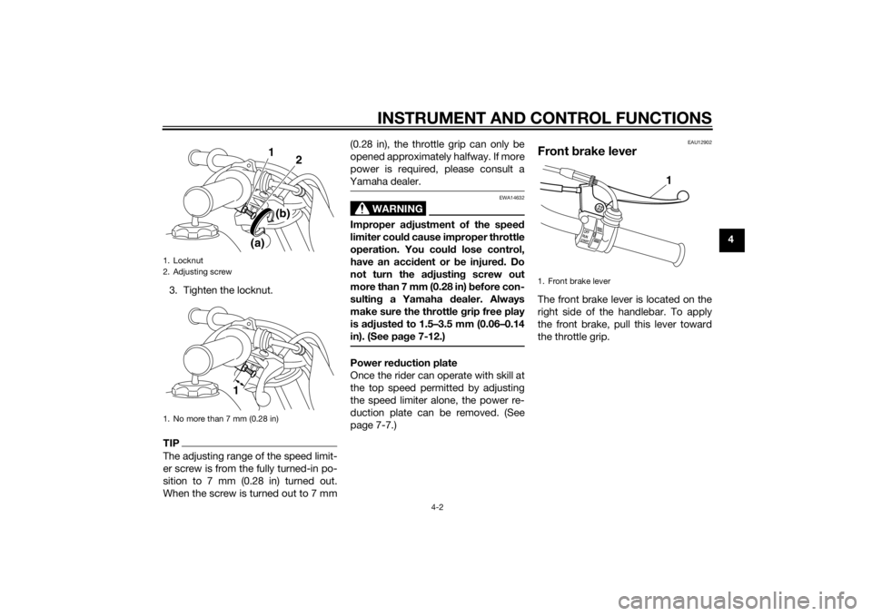
1. Loosen the locknut.
2. To increase the maximum engine power available and the maximum
speed of the motorcycle, turn the
adjusting screw in direction (a). To
decrease the maximum engine
power available and the maximum
speed of the motorcycle, turn the
adjusting screw in direction (b).
1. Engine stop switch “OFF/RUN/START”
1
U2SA81E0.book Page 1 Monday, June 2, 2014 2:00 PM
Page 29 of 76

INSTRUMENT AND CONTROL FUNCTIONS
4-2
4
3. Tighten the locknut.
TIPThe adjusting range of the speed limit-
er screw is from the fully turned-in po-
sition to 7 mm (0.28 in) turned out.
When the screw is turned out to 7 mm (0.28 in), the throttle grip can only be
opened approximately halfway. If more
power is required, please consult a
Yamaha dealer.
WARNING
EWA14632
Improper a
djustment of the spee d
limiter coul d cause improper throttle
operation. You coul d lose control,
have an acci dent or be injured . Do
not turn the a djustin g screw out
more than 7 mm (0.28 in) before con-
sultin g a Yamaha d ealer. Always
make sure the throttle grip free play
is a djuste d to 1.5–3.5 mm (0.06–0.14
in). (See pa ge 7-12.)Power re duction plate
Once the rider can operate with skill at
the top speed permitted by adjusting
the speed limiter alone, the power re-
duction plate can be removed. (See
page 7-7.)
EAU12902
Front brake leverThe front brake lever is located on the
right side of the handlebar. To apply
the front brake, pull this lever toward
the throttle grip.
1. Locknut
2. Adjusting screw
1. No more than 7 mm (0.28 in)
1
(a) (b)2
1
1. Front brake lever
1
U2SA81E0.book Page 2 Monday, June 2, 2014 2:00 PM
Page 30 of 76

INSTRUMENT AND CONTROL FUNCTIONS
4-3
4
EAU12952
Rear brake leverThe rear brake lever is located on the
left side of the handlebar. To apply the
rear brake, pull this lever toward the
handlebar grip.
EAU13183
Fuel tank capTo remove the fuel tank cap, turn it
counterclockwise, and then pull it off.
To install the fuel tank cap, insert it into
the tank opening, and then turn it
clockwise.
WARNING
EWA11092
Make sure that the fuel tank cap is
properly close d after fillin g fuel.
Leakin g fuel is a fire hazar d.
EAU13213
FuelMake sure there is sufficient gasoline in
the tank.
WARNING
EWA10882
Gasoline an d g asoline vapors are
extremely flamma ble. To avoi d fires
an d explosions an d to re duce the
risk of injury when refuelin g, follow
these instructions.1. Before refueling, turn off the en- gine and be sure that no one is sit-
ting on the vehicle. Never refuel
while smoking, or while in the vi-
cinity of sparks, open flames, or
other sources of ignition such as
the pilot lights of water heaters
and clothes dryers.
2. Do not overfill the fuel tank. Stop filling when the fuel reaches the
bottom of the filler tube. Because
fuel expands when it heats up,
heat from the engine or the sun
can cause fuel to spill out of the
fuel tank.
1. Rear brake lever
1
1. Fuel tank cap
1
U2SA81E0.book Page 3 Monday, June 2, 2014 2:00 PM
Page 32 of 76

INSTRUMENT AND CONTROL FUNCTIONS
4-5
4Your Yamaha engine has been de-
signed to use regular unleaded gaso-
line with a research octane number of
95 or higher. If knocking (or pinging)
occurs, use a gasoline of a different
brand or premium unleaded fuel. Use
of unleaded fuel will extend spark plug
life and reduce maintenance costs.
For Oceania an
d South Africa
NOTICE
ECA15591
Use only unlea ded g asoline. The use
of lead ed g asoline will cause severe
d amag e to internal en gine parts,
such as the piston rin gs as well as to
the exhaust system.Your Yamaha engine has been de-
signed to use regular unleaded gaso-
line with a research octane number of
91 or higher. If knocking (or pinging)
occurs, use a gasoline of a different brand or premium unleaded fuel. Use
of unleaded fuel will extend spark plug
life and reduce maintenance costs.
EAU13414
Fuel tank
breather hoseBefore operating the motorcycle:
Check the fuel tank breather hose
connection.
Check the fuel tank breather hose
for cracks or damage, and replace
it if necessary.
Make sure that the fuel tank
breather hose is not blocked, and
clean it if necessary.
Recommen ded fuel:
REGULAR UNLEADED GASOLINE
ONLY
Fuel tank capacity:
2.0 L (0.53 US gal, 0.44 Imp.gal)
1. Fuel tank breather hose
1
U2SA81E0.book Page 5 Monday, June 2, 2014 2:00 PM
Page 35 of 76

INSTRUMENT AND CONTROL FUNCTIONS
4-8
4
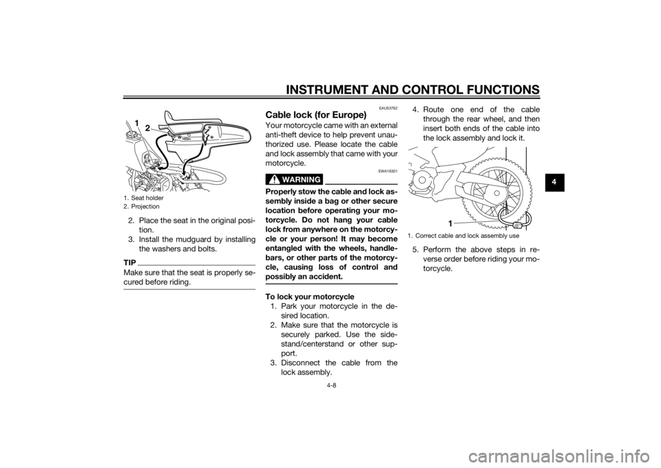
2. Place the seat in the original posi- tion.
3. Install the mudguard by installing the washers and bolts.
TIPMake sure that the seat is properly se-
cured before riding.
EAU53762
Cable lock (for Europe)Your motorcycle came with an external
anti-theft device to help prevent unau-
thorized use. Please locate the cable
and lock assembly that came with your
motorcycle.
WARNING
EWA16301
Properly stow the ca ble an d lock as-
sem bly insi de a bag or other secure
location before operatin g your mo-
torcycle. Do not han g your ca ble
lock from anywhere on the motorcy-
cle or your person! It may become
entan gle d with the wheels, han dle-
b ars, or other parts of the motorcy-
cle, causin g loss of control an d
possi bly an acci dent.To lock your motorcycle
1. Park your motorcycle in the de- sired location.
2. Make sure that the motorcycle is securely parked. Use the side-
stand/centerstand or other sup- port.
3. Disconnect the cable from the lock assembly. 4. Route one end of the cable
through the rear wheel, and then
insert both ends of the cable into
the lock assembly and lock it.
5. Perform the above steps in re- verse order before riding your mo-
torcycle.
1. Seat holder
2. Projection
12
1. Correct cable and lock assembly use
1
U2SA81E0.book Page 8 Monday, June 2, 2014 2:00 PM
Page 75 of 76

11-1
11
INDEX
AAcceleration and deceleration ................ 6-2
Air filter element, cleaning ...................... 7-9
Autolube pump, adjusting .................... 7-16BBrake lever, front .................................... 4-2
Brake lever, rear ..................................... 4-3
Brake levers, lubricating ....................... 7-17
Brake shoes, checking ......................... 7-15
Braking ................................................... 6-2CCable lock (for Europe) ........................... 4-8
Cables, checking and lubricating ......... 7-16
Carburetor, adjusting............................ 7-11
Care ........................................................ 8-1
Centerstand, checking and lubricating........................................... 7-17EEngine break-in ...................................... 6-3
Engine idling speed .............................. 7-11
Engine oil ................................................ 4-6
Engine serial number ............................ 10-1
Engine, starting a warm.......................... 6-1
Engine stop switch ................................. 4-1FFront and rear brake lever free play, adjusting ............................................. 7-14
Front fork, checking ............................. 7-17
Fuel ......................................................... 4-3
Fuel cock ................................................ 4-6
Fuel tank breather hose.......................... 4-5
Fuel tank cap .......................................... 4-3HHandlebar switch.................................... 4-1
IIdentification numbers ......................... 10-1KKickstarter .............................................. 4-7LLabels, location ...................................... 1-1MMaintenance and lubrication, periodic... 7-4
Maintenance, emission control system ................................................. 7-3
Matte color, caution ............................... 8-1
Middle and final gear cases ................... 7-9
Model label........................................... 10-1PParking ................................................... 6-4
Part locations ......................................... 3-1
Power reduction plate, removing ........... 7-7SSafety information .................................. 2-1
Seat ........................................................ 4-7
Spark arrester, cleaning ....................... 7-10
Spark plug, checking ............................. 7-6
Specifications......................................... 9-1
Speed limiter and power reduction plate ..................................................... 4-1
Starter (choke) lever ............................... 4-7
Starting and warming up a cold engine .................................................. 6-1
Starting off ............................................. 6-2
Steering, checking ............................... 7-18
Storage................................................... 8-3TThrottle grip and cable, checking and lubricating .......................................... 7-16 Throttle grip free play, checking ........... 7-12
Tires ...................................................... 7-12
Tool kit .................................................... 7-2
Transmission oil ...................................... 7-8
Troubleshooting .................................... 7-23
Troubleshooting chart........................... 7-24
VVehicle Emission Control Information
label (For Canada) .............................. 10-2
Vehicle identification number ............... 10-1WWheel bearings, checking .................... 7-18
Wheel (front).......................................... 7-19
Wheel (rear)........................................... 7-20
Wheels .................................................. 7-14
U2SA81E0.book Page 1 Monday, June 2, 2014 2:00 PM