Page 30 of 76

INSTRUMENT AND CONTROL FUNCTIONS
4-3
4
EAU12952
Rear brake leverThe rear brake lever is located on the
left side of the handlebar. To apply the
rear brake, pull this lever toward the
handlebar grip.
EAU13183
Fuel tank capTo remove the fuel tank cap, turn it
counterclockwise, and then pull it off.
To install the fuel tank cap, insert it into
the tank opening, and then turn it
clockwise.
WARNING
EWA11092
Make sure that the fuel tank cap is
properly close d after fillin g fuel.
Leakin g fuel is a fire hazar d.
EAU13213
FuelMake sure there is sufficient gasoline in
the tank.
WARNING
EWA10882
Gasoline an d g asoline vapors are
extremely flamma ble. To avoi d fires
an d explosions an d to re duce the
risk of injury when refuelin g, follow
these instructions.1. Before refueling, turn off the en- gine and be sure that no one is sit-
ting on the vehicle. Never refuel
while smoking, or while in the vi-
cinity of sparks, open flames, or
other sources of ignition such as
the pilot lights of water heaters
and clothes dryers.
2. Do not overfill the fuel tank. Stop filling when the fuel reaches the
bottom of the filler tube. Because
fuel expands when it heats up,
heat from the engine or the sun
can cause fuel to spill out of the
fuel tank.
1. Rear brake lever
1
1. Fuel tank cap
1
U2SA81E0.book Page 3 Monday, June 2, 2014 2:00 PM
Page 38 of 76

OPERATION AND IMPORTANT RIDING POINTS
6-1
6
EAU15952
Read the Owner’s Manual carefully to
become familiar with all controls. If
there is a control or function you do not
understand, ask your Yamaha dealer.
WARNING
EWA10272
Failure to familiarize yourself with
the controls can lead to loss of con-
trol, which coul d cause an acci dent
or injury.
EAU4088A
Startin g an d warmin g up a
col d en gine1. Turn the fuel cock lever to “O”
(on).
2. Set the engine stop switch to “START”.
3. Turn the starter (choke) on and completely close the throttle. (See
page 4-7.)
4. While applying the front or rear brake, start the engine by pushing
the kickstarter lever down.
5. After starting the engine, move the starter (choke) back halfway.
6. When the engine is warm, turn the starter (choke) off and set the en-
gine stop switch to “RUN”.TIPThe engine is warm when it responds
quickly to the throttle with the starter
(choke) turned off.NOTICE
ECA11043
For maximum en gine life, never ac-
celerate har d when the en gine is
col d!
EAU16661
Startin g a warm en gineFollow the same procedure as for
starting a cold engine with the excep-
tion that the starter (choke) is not re-
quired when the engine is warm.
Instead, start the engine with the throt-
tle slightly open.TIPIf the engine does not start after sever-
al kicks, try again with the throttle 1/4
to 1/2 open.
U2SA81E0.book Page 1 Monday, June 2, 2014 2:00 PM
Page 46 of 76
PERIODIC MAINTENANCE AND ADJUSTMENT
7-5
7
TIPThe air filter needs more frequent service if you are riding in unusually wet or dusty areas.10
*Transmission oil
Check for oil leakage .Correct if necessary.Change.
11
*Front and rear brake
lever pivot
Apply lithium-soap-based grease lightly.
12
*
Centerstand pivot
Check operation.Apply lithium-soap-based grease lightly.
13
*Shock absorber
assemblies
Check operation and for oil leakage.Replace if necessary.
14
*
Control cables
Apply Yamaha cable lubricant or other suitable
cable lubricant.
15
*Throttle grip
Check operation.Check throttle grip free play, and adjust if
necessary.Apply Yamaha cable lubricant or other suitable
cable lubricant.
NO. ITEM CHECK OR MAINTENANCE JOB
INITIAL
THEREAFTER
EVERY
1
month 3
months 6
months 6
months 12
months
8* Chassis fastenersCorrect if necessary.
A
9* utolube pumpCheck operation.Correct if necessary. Check all chassis fitting and fasteners.
U2SA81E0.book Page 5 Monday, June 2, 2014 2:00 PM
Page 63 of 76

PERIODIC MAINTENANCE AND ADJUSTMENT
7-22
7
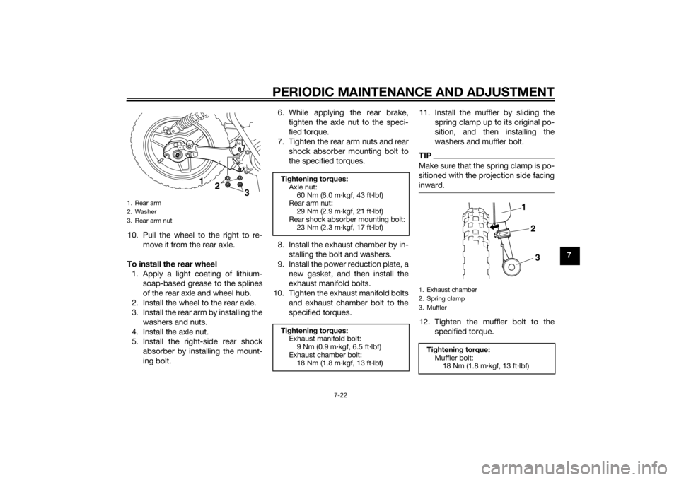
10. Pull the wheel to the right to re-
move it from the rear axle.
To install the rear wheel 1. Apply a light coating of lithium- soap-based grease to the splines
of the rear axle and wheel hub.
2. Install the wheel to the rear axle.
3. Install the rear arm by installing the washers and nuts.
4. Install the axle nut.
5. Install the right-side rear shock absorber by installing the mount-
ing bolt. 6. While applying the rear brake,
tighten the axle nut to the speci-
fied torque.
7. Tighten the rear arm nuts and rear shock absorber mounting bolt to
the specified torques.
8. Install the exhaust chamber by in- stalling the bolt and washers.
9. Install the power reduction plate, a new gasket, and then install the
exhaust manifold bolts.
10. Tighten the exhaust manifold bolts and exhaust chamber bolt to the
specified torques. 11. Install the muffler by sliding the
spring clamp up to its original po-
sition, and then installing the
washers and muffler bolt.
TIPMake sure that the spring clamp is po-
sitioned with the projection side facing
inward.12. Tighten the muffler bolt to thespecified torque.
1. Rear arm
2. Washer
3. Rear arm nut
12
3
Tightenin g torques:
Axle nut: 60 Nm (6.0 m·kgf, 43 ft·lbf)
Rear arm nut:
29 Nm (2.9 m·kgf, 21 ft·lbf)
Rear shock absorber mounting bolt: 23 Nm (2.3 m·kgf, 17 ft·lbf)
Ti ghtenin g torques:
Exhaust manifold bolt:
9 Nm (0.9 m·kgf, 6.5 ft·lbf)
Exhaust chamber bolt: 18 Nm (1.8 m·kgf, 13 ft·lbf)
1. Exhaust chamber
2. Spring clamp
3. Muffler
Tightenin g torque:
Muffler bolt:
18 Nm (1.8 m·kgf, 13 ft·lbf)
1
2
3
U2SA81E0.book Page 22 Monday, June 2, 2014 2:00 PM