2015 YAMAHA PW50 brake
[x] Cancel search: brakePage 62 of 76

PERIODIC MAINTENANCE AND ADJUSTMENT
7-21
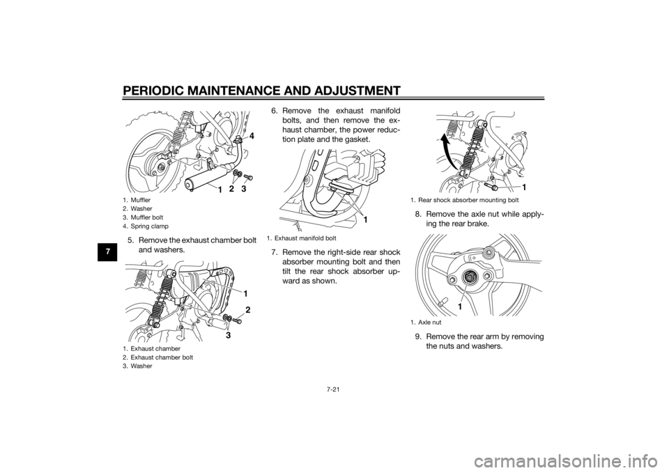
75. Remove the exhaust chamber bolt
and washers. 6. Remove the exhaust manifold
bolts, and then remove the ex-
haust chamber, the power reduc-
tion plate and the gasket.
7. Remove the right-side rear shock absorber mounting bolt and then
tilt the rear shock absorber up-
ward as shown. 8. Remove the axle nut while apply-
ing the rear brake.
9. Remove the rear arm by removing the nuts and washers.
1. Muffler
2. Washer
3. Muffler bolt
4. Spring clamp
1. Exhaust chamber
2. Exhaust chamber bolt
3. Washer
3
1
2 4
2
1
3
1. Exhaust manifold bolt
1
1. Rear shock absorber mounting bolt
1. Axle nut
1
1
U2SA81E0.book Page 21 Monday, June 2, 2014 2:00 PM
Page 63 of 76

PERIODIC MAINTENANCE AND ADJUSTMENT
7-22
7
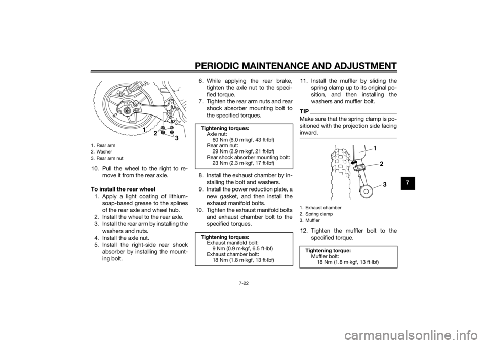
10. Pull the wheel to the right to re-
move it from the rear axle.
To install the rear wheel 1. Apply a light coating of lithium- soap-based grease to the splines
of the rear axle and wheel hub.
2. Install the wheel to the rear axle.
3. Install the rear arm by installing the washers and nuts.
4. Install the axle nut.
5. Install the right-side rear shock absorber by installing the mount-
ing bolt. 6. While applying the rear brake,
tighten the axle nut to the speci-
fied torque.
7. Tighten the rear arm nuts and rear shock absorber mounting bolt to
the specified torques.
8. Install the exhaust chamber by in- stalling the bolt and washers.
9. Install the power reduction plate, a new gasket, and then install the
exhaust manifold bolts.
10. Tighten the exhaust manifold bolts and exhaust chamber bolt to the
specified torques. 11. Install the muffler by sliding the
spring clamp up to its original po-
sition, and then installing the
washers and muffler bolt.
TIPMake sure that the spring clamp is po-
sitioned with the projection side facing
inward.12. Tighten the muffler bolt to thespecified torque.
1. Rear arm
2. Washer
3. Rear arm nut
12
3
Tightenin g torques:
Axle nut: 60 Nm (6.0 m·kgf, 43 ft·lbf)
Rear arm nut:
29 Nm (2.9 m·kgf, 21 ft·lbf)
Rear shock absorber mounting bolt: 23 Nm (2.3 m·kgf, 17 ft·lbf)
Ti ghtenin g torques:
Exhaust manifold bolt:
9 Nm (0.9 m·kgf, 6.5 ft·lbf)
Exhaust chamber bolt: 18 Nm (1.8 m·kgf, 13 ft·lbf)
1. Exhaust chamber
2. Spring clamp
3. Muffler
Tightenin g torque:
Muffler bolt:
18 Nm (1.8 m·kgf, 13 ft·lbf)
1
2
3
U2SA81E0.book Page 22 Monday, June 2, 2014 2:00 PM
Page 64 of 76

PERIODIC MAINTENANCE AND ADJUSTMENT
7-23
713. Adjust the brake lever free play.
(See page 7-14.)
14. Install the seat.
EAU25852
Trou bleshootin gAlthough Yamaha motorcycles receive
a thorough inspection before shipment
from the factory, trouble may occur
during operation. Any problem in the
fuel, compression, or ignition systems,
for example, can cause poor starting
and loss of power.
The following troubleshooting chart
represents a quick and easy procedure
for checking these vital systems your-
self. However, should your motorcycle
require any repair, take it to a Yamaha
dealer, whose skilled technicians have
the necessary tools, experience, and
know-how to service the motorcycle
properly.
Use only genuine Yamaha replace-
ment parts. Imitation parts may look
like Yamaha parts, but they are often
inferior, have a shorter service life and
can lead to expensive repair bills.
WARNING
EWA15142
When checkin g the fuel system, do
not smoke, an d make sure there are
no open flames or sparks in the ar-
ea, inclu din g pilot lig hts from water heaters or furnaces. Gasoline or
g
asoline vapors can i gnite or ex-
plod e, causin g severe injury or prop-
erty damag e.
U2SA81E0.book Page 23 Monday, June 2, 2014 2:00 PM
Page 67 of 76

MOTORCYCLE CARE AND STORAGE8-2
8
d
eter gent resi due usin g plenty
of water, as it is harmful to plas-
tic parts.
Do not use any harsh chemical
prod ucts on plastic parts. Be
sure to avoi d usin g cloths or
spon ges which have b een in
contact with stron g or a brasive
cleanin g prod ucts, solvent or
thinner, fuel ( gasoline), rust re-
movers or inhi bitors, brake flui d,
antifreeze or electrolyte.
Do not use hi gh-pressure wash-
ers or steam-jet cleaners since
they cause water seepag e and
d eterioration in the followin g ar-
eas: seals (of wheel an d swin g-
arm bearin gs, fork an d b rakes),
electric components (couplers,
connectors, an d switches),
b reather hoses an d vents.
After normal useRemove dirt with warm water, a mild
detergent, and a soft, clean sponge,
and then rinse thoroughly with clean
water. Use a toothbrush or bottlebrush
for hard-to-reach areas. Stubborn dirt and insects will come off more easily if
the area is covered with a wet cloth for
a few minutes before cleaning.
After riding in the rain or near the sea
Since sea salt is extremely corrosive,
carry out the following steps after each
ride in the rain or near the sea.
1. Clean the motorcycle with cold water and a mild detergent, after
the engine has cooled down.
NOTICE: Do not use warm wa-
ter since it increases the corro-
sive action of the salt.
[ECA10792]
2. Apply a corrosion protection spray on all metal, including chrome-
and nickel-plated, surfaces to pre-
vent corrosion.
After cleanin g
1. Dry the motorcycle with a chamois or an absorbing cloth.
2. Use a chrome polish to shine chrome, aluminum and stainless-
steel parts. 3. To prevent corrosion, it is recom-
mended to apply a corrosion pro-
tection spray on all metal,
including chrome- and nickel-plat-
ed, surfaces.
4. Use spray oil as a universal clean- er to remove any remaining dirt.
5. Touch up minor paint damage caused by stones, etc.
6. Wax all painted surfaces.
7. Let the motorcycle dry completely before storing or covering it.
WARNING
EWA14502
Contaminants on the brakes or tires
can cause loss of control. Make sure that there is no oil or
wax on the tires.
If necessary, wash the tires with
warm water an d a mil d d eter-
g ent. Before ri din g at hi gher
speed s, test the motorcycle’s
b rakin g performance an d cor-
nering b ehavior.
U2SA81E0.book Page 2 Monday, June 2, 2014 2:00 PM
Page 71 of 76

SPECIFICATIONS
9-2
9
Chassis:Frame type:Backbone
Caster angle:
25.50 °
Trail: 50 mm (2.0 in)Front tire:Type:
With tube
Size: 2.50-10 4PR
Manufacturer/model: BRIDGESTONE/M29
Manufacturer/model:
PW50 IRC/Z MARK II (ZAF)
PW50F IRC/Z MARK II
PW50F1 IRC/Z MARK II
Speed rating: 100 km/h (62 mph)Rear tire:Type:With tube
Size: 2.50-10 4PR
Manufacturer/model:
BRIDGESTONE/M29
Manufacturer/model: PW50 IRC/Z MARK II (ZAF)
PW50F IRC/Z MARK II
PW50F1 IRC/Z MARK II
Speed rating:
100 km/h (62 mph)
Loa din g:Maximum rider weight:
25.0 kg (55 lb)Tire air pressure (measure d on col d
tires):
Front:
100 kPa (1.00 kgf/cm², 15 psi)
Rear:
100 kPa (1.00 kgf/cm², 15 psi)
Front wheel:Wheel type:Panel wheel
Rim size:
10x1.50Rear wheel:Wheel type:Panel wheel
Rim size:
10x1.50Front brake:Type:
Drum brake
Operation:
Right hand operationRear brake:Type:
Drum brake
Operation:
Left hand operationFront suspension:Type:Telescopic fork
Spring/shock absorber type:
Coil spring/oil damper Wheel travel:
60 mm (2.4 in)
Rear suspension:Type:
Unit swing
Spring/shock absorber type: Coil spring/oil damper
Wheel travel: 50 mm (2.0 in)Electrical system:Ignition system:CDI
U2SA81E0.book Page 2 Monday, June 2, 2014 2:00 PM
Page 75 of 76

11-1
11
INDEX
AAcceleration and deceleration ................ 6-2
Air filter element, cleaning ...................... 7-9
Autolube pump, adjusting .................... 7-16BBrake lever, front .................................... 4-2
Brake lever, rear ..................................... 4-3
Brake levers, lubricating ....................... 7-17
Brake shoes, checking ......................... 7-15
Braking ................................................... 6-2CCable lock (for Europe) ........................... 4-8
Cables, checking and lubricating ......... 7-16
Carburetor, adjusting............................ 7-11
Care ........................................................ 8-1
Centerstand, checking and lubricating........................................... 7-17EEngine break-in ...................................... 6-3
Engine idling speed .............................. 7-11
Engine oil ................................................ 4-6
Engine serial number ............................ 10-1
Engine, starting a warm.......................... 6-1
Engine stop switch ................................. 4-1FFront and rear brake lever free play, adjusting ............................................. 7-14
Front fork, checking ............................. 7-17
Fuel ......................................................... 4-3
Fuel cock ................................................ 4-6
Fuel tank breather hose.......................... 4-5
Fuel tank cap .......................................... 4-3HHandlebar switch.................................... 4-1
IIdentification numbers ......................... 10-1KKickstarter .............................................. 4-7LLabels, location ...................................... 1-1MMaintenance and lubrication, periodic... 7-4
Maintenance, emission control system ................................................. 7-3
Matte color, caution ............................... 8-1
Middle and final gear cases ................... 7-9
Model label........................................... 10-1PParking ................................................... 6-4
Part locations ......................................... 3-1
Power reduction plate, removing ........... 7-7SSafety information .................................. 2-1
Seat ........................................................ 4-7
Spark arrester, cleaning ....................... 7-10
Spark plug, checking ............................. 7-6
Specifications......................................... 9-1
Speed limiter and power reduction plate ..................................................... 4-1
Starter (choke) lever ............................... 4-7
Starting and warming up a cold engine .................................................. 6-1
Starting off ............................................. 6-2
Steering, checking ............................... 7-18
Storage................................................... 8-3TThrottle grip and cable, checking and lubricating .......................................... 7-16 Throttle grip free play, checking ........... 7-12
Tires ...................................................... 7-12
Tool kit .................................................... 7-2
Transmission oil ...................................... 7-8
Troubleshooting .................................... 7-23
Troubleshooting chart........................... 7-24
VVehicle Emission Control Information
label (For Canada) .............................. 10-2
Vehicle identification number ............... 10-1WWheel bearings, checking .................... 7-18
Wheel (front).......................................... 7-19
Wheel (rear)........................................... 7-20
Wheels .................................................. 7-14
U2SA81E0.book Page 1 Monday, June 2, 2014 2:00 PM