2015 YAMAHA GRIZZLY 450 brake light
[x] Cancel search: brake lightPage 65 of 170

6-4
6
reverse, make sure there are no people or ob-
stacles behind you. When it is safe to proceed,
go slowly.
1. Bring the ATV to a complete stop.
2. Apply the brake pedal. The drive select lever
cannot be shifted into or from reverse or park
without applying the brake pedal.
3. Shift from neutral to reverse or from reverse to park and vice versa by moving the drive se-
lect lever along the shift guide.
TIPWhen in reverse, the reverse indicator light
should come on. If the indicator light does not
come on, have a Yamaha dealer check the elec-
trical circuit.
Due to the synchronizing mechanism in the en-
gine, the indicator light may not come on until
the ATV starts moving. 1. Drive select lever
2. L (Low-range)
3. H (High-range)
4. N (Neutral)
5. R (Reverse)
6. P (Park)
2L3H4N5R6P
1
U2LC61E0.book Page 4 Wednesday, February 26, 2014 3:56 PM
Page 100 of 170

8-8
8
23 Final gear oil• Change.
• Check ATV for oil leakage, and correct if neces-
sary. √ √√√
24 Cooling system • Check coolant level and ATV for coolant leakage,
and correct if necessary. √√√√√
• Replace coolant. Every 2 years
25 *Moving parts and
cables • Lubricate.
√√√√
26 *Drive select lever
safety system cable • Check operation and adjust or replace if neces-
sary. √√√
27 *Throttle lever • Check operation.
• Check throttle lever free play, and adjust if neces-
sary.
• Lubricate cable and lever housing. √√√√√
28 *Front and rear
brake switches • Check operation and correct if necessary.
√√√√√
29 *Lights and switches • Check operation and correct if necessary.
• Adjust headlight beams.
√√√√√
NO. ITEM
CHECK OR MAINTENANCE
JOB INITIAL EVERY
Whichev-
er comes first month136612
km (mi) 320
(200) 1300
(800) 2500
(1600) 2500
(1600) 5000
(3200)
hours 20 80 160 160 320U2LC61E0.book Page 8 Wednesday, February 26, 2014 3:56 PM
Page 139 of 170

8-47
8
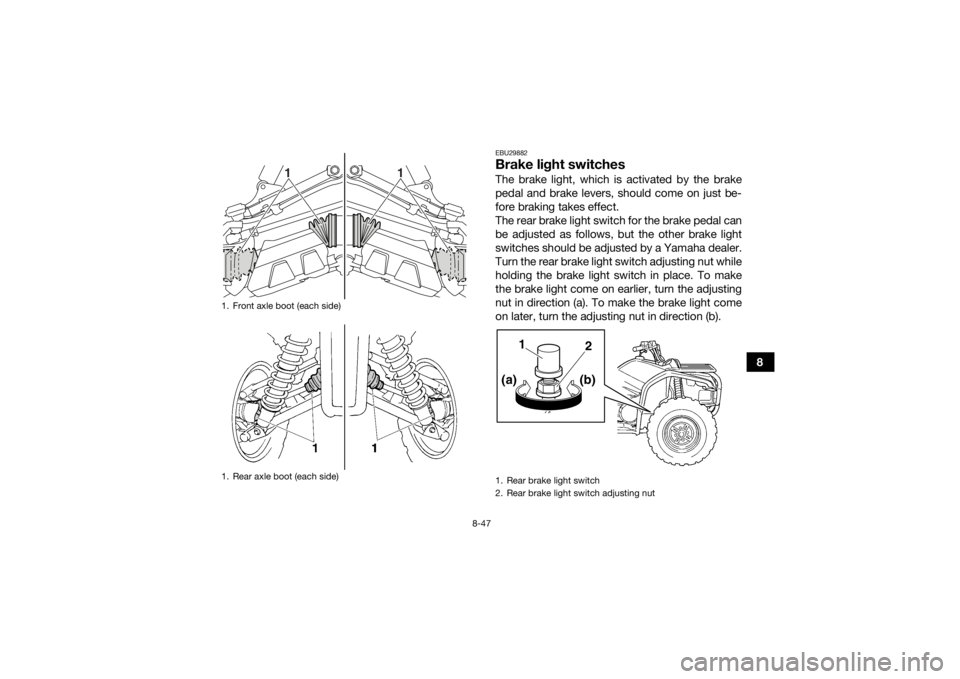
EBU29882Brake light switchesThe brake light, which is activated by the brake
pedal and brake levers, should come on just be-
fore braking takes effect.
The rear brake light switch for the brake pedal can
be adjusted as follows, but the other brake light
switches should be adjusted by a Yamaha dealer.
Turn the rear brake light switch adjusting nut while
holding the brake light switch in place. To make
the brake light come on earlier, turn the adjusting
nut in direction (a). To make the brake light come
on later, turn the adjusting nut in direction (b).
1. Front axle boot (each side)
1. Rear axle boot (each side)
1
1
1. Rear brake light switch
2. Rear brake light switch adjusting nut
1
2(b)
(a)
U2LC61E0.book Page 47 Wednesday, February 26, 2014 3:56 PM
Page 152 of 170

8-60
8
EBU25623Replacing the tail/brake light bulbIf the tail/brake light bulb burns out, replace it as
follows.1. Remove the tail/brake light assembly by re- moving the nuts together with the washers. 2. Remove the tail/brake light bulb holder (to-
gether with the bulb) by turning it counter-
clockwise.1. Headlight beam adjusting screw
1. Tail/brake light assembly
2. Nut
U2LC61E0.book Page 60 Wednesday, February 26, 2014 3:56 PM
Page 153 of 170

8-61
8
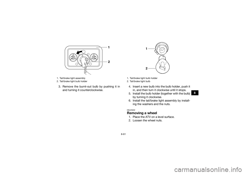
3. Remove the burnt-out bulb by pushing it in
and turning it counterclockwise. 4. Insert a new bulb into the bulb holder, push it
in, and then turn it clockwise until it stops.
5. Install the bulb holder (together with the bulb) by turning it clockwise.
6. Install the tail/brake light assembly by install- ing the washers and the nuts.
EBU25652Removing a wheel1. Place the ATV on a level surface.
2. Loosen the wheel nuts.
1. Tail/brake light assembly
2. Tail/brake light bulb holder
1. Tail/brake light bulb holder
2. Tail/brake light bulb
U2LC61E0.book Page 61 Wednesday, February 26, 2014 3:56 PM
Page 164 of 170

10-4
10
Rear:22.0 kPa (0.220 kgf/cm², 3.2 psi)
Front wheel:Wheel type:
Panel wheel
Rim size: 12 x 6.0ATRear wheel:Wheel type:
Panel wheel
Rim size: 12 x 7.5ATFront brake:Type:
Disc brake
Operation: Right hand operation
Specified brake fluid: DOT 4Rear brake:Type:Wet multiple disc brake
Operation: Left hand and right foot operationFront suspension:Type:Double wishbone
Spring/shock absorber type: Coil spring/oil damper
Wheel travel:
160 mm (6.3 in)
Rear suspension:Type:Double wishbone
Spring/shock absorber type:
Coil spring/oil damper
Wheel travel: 180 mm (7.1 in)Electrical system:Ignition system:
DC CDI
Charging system: AC magnetoBattery:Model:
YTX20L-BS
Voltage, capacity: 12 V, 18.0 AhHeadlight:Bulb type:
Krypton bulbBulb voltage, wattage × quantity:Headlight:
12 V, 30.0/30.0 W × 2
Tail/brake light:
12 V, 5.0/21.0 W × 1
Meter lighting: EL (Electroluminescent)
Neutral indicator light: LED
Reverse indicator light:
LED
U2LC61E0.book Page 4 Wednesday, February 26, 2014 3:56 PM
Page 168 of 170

12-1
12
INDEX
AAccessories and loading ................................................ 6-6
Accessories, auxiliary jack ........................................... 4-24
Air filter element, cleaning ............................................ 8-30
Axle boots .................................................................... 8-46BBattery .......................................................................... 8-52
Brake fluid, changing ...................................................8-40
Brake fluid level, checking ........................................... 8-39
Brake lever free play, checking the front ..................... 8-40
Brake lever, front .......................................................... 4-14
Brake levers, checking and lubricating ........................ 8-48
Brake light switches ..................................................... 8-47
Brake pads and friction plates, checking ..................... 8-38
Brake pedal and rear brake lever ................................. 4-14
Brake pedal, checking and lubricating ........................ 8-49
Brakes .......................................................................... 8-38
Brakes, front and rear .................................................... 5-3CCables, checking and lubricating ................................. 8-48
Carburetor, adjusting ...................................................8-35
Carrier, front ................................................................. 4-22
Carrier, rear .................................................................. 4-22
Chassis fasteners ........................................................... 5-7
Cleaning ......................................................................... 9-1
Coolant ................................................................. 5-3, 8-26
Coolant temperature warning light ................................. 4-3DDifferential gear oil ............................................... 5-3, 8-24Drive select lever .......................................................... 4-15
Drive select lever and driving in reverse ........................ 6-3
Drive select lever safety system cable, adjusting ........ 8-38
Drive shaft universal joint, lubricating .......................... 8-50
EEngine break-in .............................................................. 6-5
Engine, cold start ........................................................... 6-1
Engine idling speed ...................................................... 8-35
Engine oil ....................................................................... 5-3
Engine oil and oil filter cartridge .................................. 8-16
Engine, starting a warm ................................................. 6-3
Engine stop switch ......................................................... 4-7
EPS warning light (for EPS model) ................................. 4-3FFinal gear oil ......................................................... 5-3, 8-21
Four-wheel-drive/differential gear lock indicator ........... 4-4
Fuel ...................................................................... 4-15, 5-3
Fuel cock ...................................................................... 4-17
Fuel gauge ..................................................................... 4-6
Fuel tank cap ............................................................... 4-15
Fuses, replacing ........................................................... 8-55HHandlebar switches ....................................................... 4-7
Headlight beam, adjusting ........................................... 8-59
Headlight bulb, replacing ............................................. 8-58
High-range indicator light .............................................. 4-2
Horn switch .................................................................... 4-7IIdentification numbers ................................................. 11-1
U2LC61E0.book Page 1 Wednesday, February 26, 2014 3:56 PM
Page 169 of 170

12-2
12
Indicator lights and warning lights ................................. 4-2
Instruments, lights and switches ................................... 5-7LLabel locations ............................................................... 1-1
Light switch .................................................................... 4-7
Low-range indicator light ............................................... 4-2MMain switch .................................................................... 4-1
Maintenance and lubrication chart ................................ 8-5
Maintenance chart, emission control system ................ 8-3
Model label .................................................................. 11-1
Multi-function display .................................................... 4-5NNeutral indicator light ..................................................... 4-2OOn-Command differential gear lock switch ................. 4-10
On-Command four-wheel-drive switch ......................... 4-9
Override switch .............................................................. 4-8
Owner’s manual and tool kit .......................................... 8-2PPanels, removing and installing ................................... 8-10
Park indicator light ......................................................... 4-3
Parking ........................................................................... 6-5
Parking on a slope ......................................................... 6-6
Part locations ................................................................. 3-1RRear brake, adjusting the lever, pedal free play and pedal height ............................................................... 8-41
Rear knuckle pivots, lubricating .................................. 8-51
Reverse indicator light ................................................... 4-3
Riding your ATV ............................................................. 7-1
SSafety information .......................................................... 2-1
Seat .............................................................................. 4-19
Shock absorber assemblies, adjusting the front and
rear ............................................................................ 4-22
Spark arrester, cleaning ............................................... 8-33
Spark plug, checking ................................................... 8-14
Specifications .............................................................. 10-1
Speed limiter ................................................................ 4-13
Stabilizer bushes, checking .......... ............................... 8-51
Starter (choke) ............................................................. 4-18
Start switch .................................................................... 4-7
Steering shaft, lubricating ............................................ 8-52
Storage .......................................................................... 9-2
Storage compartments ................................................ 4-20TTail/brake light bulb, replacing .................................... 8-60
Throttle lever ......................................................... 4-12, 5-4
Throttle lever free play, adjusting ................................ 8-37
Tires ............................................................................... 5-4
Troubleshooting ........................................................... 8-63
Troubleshooting charts ................................................ 8-64VValve clearance ............................................................ 8-37
V-belt case drain plug .................................................. 8-35
V-belt cooling duct check hose ................................... 8-34
Vehicle identification number ...................................... 11-1WWheel hub bearings, checking .................................... 8-49
Wheel, installing ........................................................... 8-62
Wheel, removing .......................................................... 8-61
U2LC61E0.book Page 2 Wednesday, February 26, 2014 3:56 PM