Page 89 of 104

Maintenance
83
EJU33769
Maintenance
Periodic checks and lubrication will keep
your watercraft in the safest and most effi-
cient condition possible. Therefore, make
sure to carry out the periodic maintenance.
Safety is an obligation of the watercraft own-
er. Proper maintenance must be carried out
to keep the exhaust emission and sound lev-
els within the regulated limits. The most im-
portant points of watercraft inspection and
lubrication are explained on the following pa-
ges.
See a Yamaha dealer for genuine Yamaha re-
placement parts and optional accessories
designed for your watercraft.
Remember, failures that are the result of the
installation of parts or accessories which are
not qualitatively equivalent to genuine
Yamaha parts are not covered by the limited warranty.
Maintenance, replacement, or repair of
the emission control devices and system
may be performed by any marine SI engine
repair establishment or individual. War-
ranty repair, however, must be performed
at an authorized Yamaha marine dealer-
ship.
WARNING
EWJ00312
Be sure to turn off the engine when you
perform maintenance unless otherwise
specified. If you are not familiar with ma-
chine servicing, this work should be done
by a Yamaha dealer or other qualified me-
chanic.
EJU33803Tool kit
A tool kit is included with this watercraft. Pla-
ce the tool kit in a waterproof bag and always carry it with you whenever you use the water-
craft.
EJU42021Removing and installing the engine
cover
The engine cover is removable.
To remove the engine cover:
(1) Remove the seats. (See page 40 for seat
removal and installation procedures.)
(2) Remove the engine cover screws.
1 Tool bag
2 Screwdriver
3 Garden hose adapter
4 10/12 mm box wrench
5 Pliers
6 10/12 mm open-end wrench
1 Engine cover screw
1
UF3L71E0.book Page 83 Monday, June 30, 2014 9:06 AM
Page 90 of 104
Maintenance
84
(3) Lift up the engine cover to remove it.
To install the engine cover:
(1) Place the engine cover in its original po-sition, and then push it down.
(2) Install the engine cover screws, and then tighten them to the specified torque.
(3) Securely install the seats in their original positions.
1Engine cover
Tightening torque:
Engine cover screw:
4.5 Nm (0.46 kgf-m, 3.3 ft-lb)
1
UF3L71E0.book Page 84 Monday, June 30, 2014 9:06 AM
Page 99 of 104

Trouble recovery
93
(2) Remove any weeds or debris fromaround the jet intake, drive shaft, impel-
ler, jet pump housing, and jet thrust noz-
zle.
If debris is difficult to remove, consult a
Yamaha dealer.
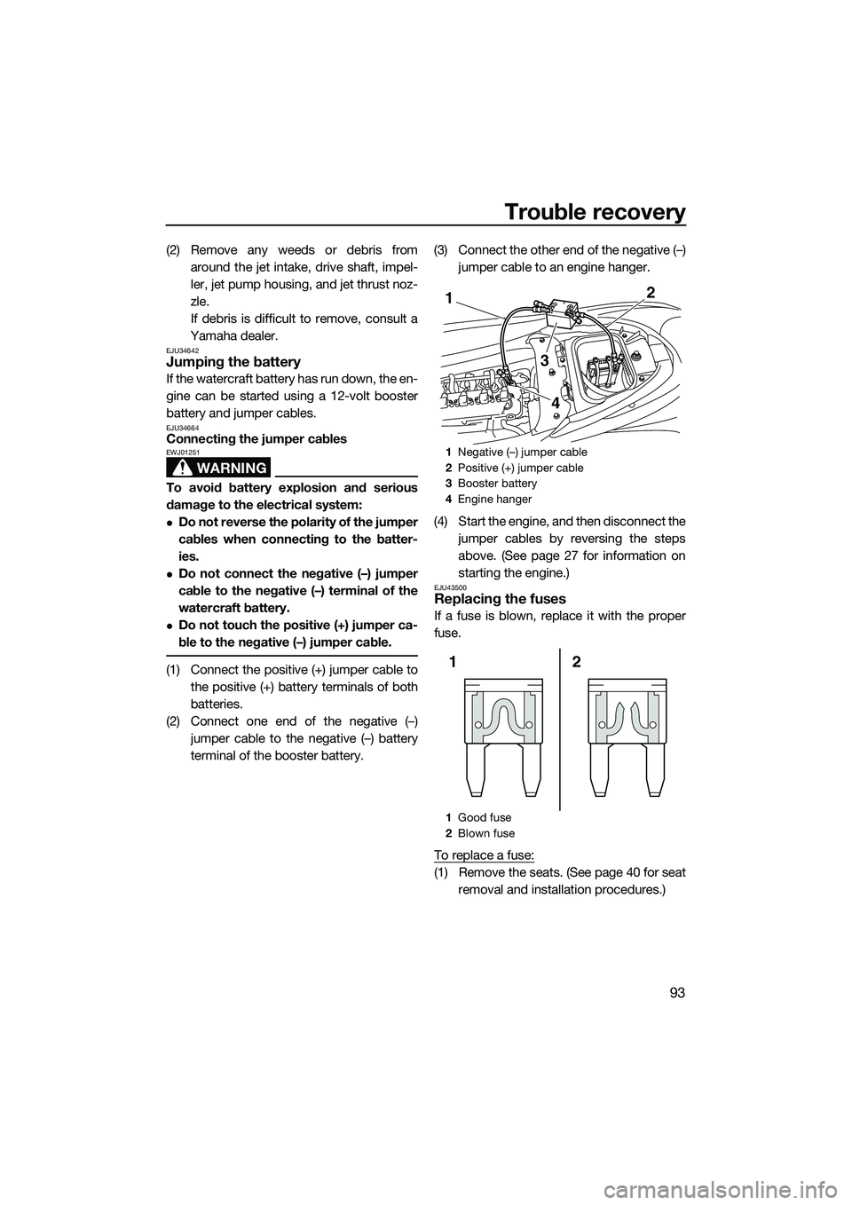
EJU34642Jumping the battery
If the watercraft battery has run down, the en-
gine can be started using a 12-volt booster
battery and jumper cables.
EJU34664Connecting the jumper cables
WARNING
EWJ01251
To avoid battery explosion and serious
damage to the electrical system:
Do not reverse the polarity of the jumper
cables when connecting to the batter-
ies.
Do not connect the negative (–) jumper
cable to the negative (–) terminal of the
watercraft battery.
Do not touch the positive (+) jumper ca-
ble to the negative (–) jumper cable.
(1) Connect the positive (+) jumper cable to the positive (+) battery terminals of both
batteries.
(2) Connect one end of the negative (–) jumper cable to the negative (–) battery
terminal of the booster battery. (3) Connect the other end of the negative (–)
jumper cable to an engine hanger.
(4) Start the engine, and then disconnect the jumper cables by reversing the steps
above. (See page 27 for information on
starting the engine.)
EJU43500Replacing the fuses
If a fuse is blown, replace it with the proper
fuse.
To replace a fuse:
(1) Remove the seats. (See page 40 for seatremoval and installation procedures.)
1Negative (–) jumper cable
2 Positive (+) jumper cable
3 Booster battery
4 Engine hanger
1 Good fuse
2 Blown fuse
2
3
1
4
2
1
UF3L71E0.book Page 93 Monday, June 30, 2014 9:06 AM
Page 100 of 104

Trouble recovery
94
(2) Remove the electrical box cover.
(3) While pushing both sides of the fuse boxcover inward, pull the cover toward the
bow and remove it.
(4) When replacing a fuse, remove the fuse using the fuse puller. Install a spare fuse
of the proper amperage. WARNING! Do
not use fuses of a different amperage
than recommended. Substitution with
a fuse that has an improper rating can cause extensive electrical system
damage and possible fire.
[EWJ00803]
(5) Securely install the fuse box cover in its
original position.
(6) Securely install the electrical box cover in its original position.
(7) Securely install the seats in their original positions.
1Electrical box cover
1 Fuse box cover
1
1
1Electronic throttle valve fuse
2 Fuel pump fuse
3 Main relay drive fuse
4 Main fuse
5 Fuse puller
6 Battery fuse
7 Bilge pump fuse
8 Security system fuse
9 Spare fuse
Fuse amperage:
Electronic throttle valve fuse: 10 A
Fuel pump fuse: 10 A
Main relay drive fuse:
10 A
Main fuse: 20 A
Battery fuse: 30 A
Bilge pump fuse:
3 A
Security system fuse: 3 A
1
9
23 4 5 6
87
UF3L71E0.book Page 94 Monday, June 30, 2014 9:06 AM