2015 YAMAHA FJR1300A Fork
[x] Cancel search: ForkPage 55 of 120

INSTRUMENT AND CONTROL FUNCTIONS
3-40
3
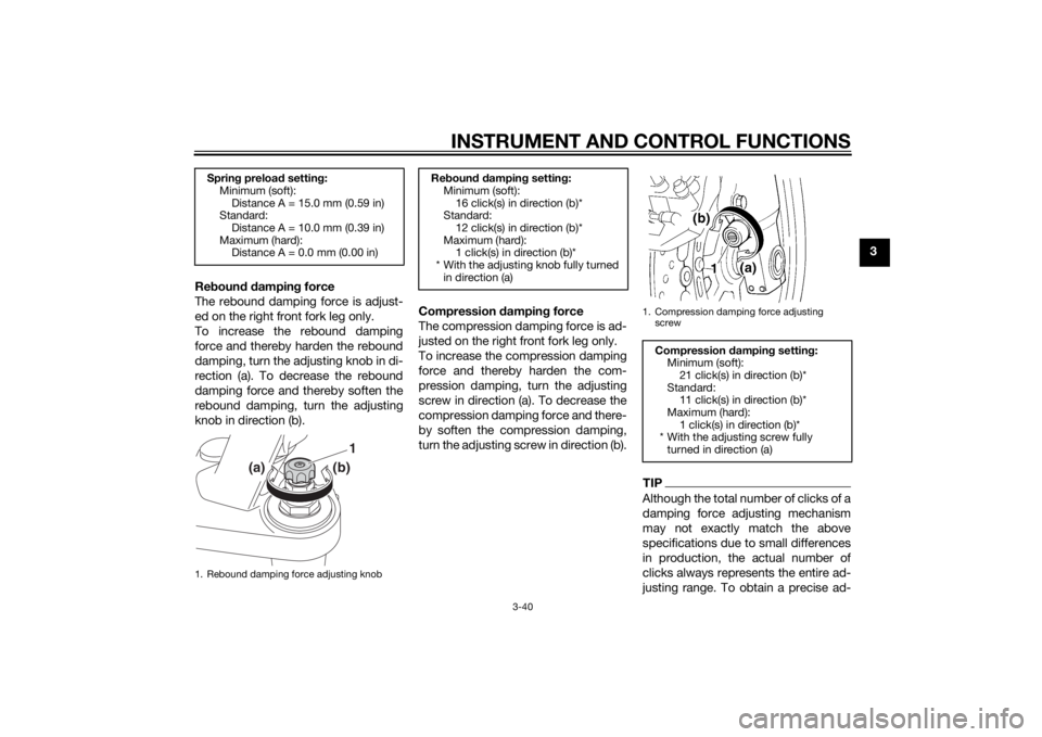
Re boun d d ampin g force
The rebound damping force is adjust-
ed on the right front fork leg only.
To increase the rebound damping
force and thereby harden the rebound
damping, turn the adjusting knob in di-
rection (a). To decrease the rebound
damping force and thereby soften the
rebound damping, turn the adjusting
knob in direction (b). Compression
dampin g force
The compression damping force is ad-
justed on the right front fork leg only.
To increase the compression damping
force and thereby harden the com-
pression damping, turn the adjusting
screw in direction (a). To decrease the
compression damping force and there-
by soften the compression damping,
turn the adjusting screw in direction (b).
TIPAlthough the total number of clicks of a
damping force adjusting mechanism
may not exactly match the above
specifications due to small differences
in production, the actual number of
clicks always represents the entire ad-
justing range. To obtain a precise ad-
Sprin g preloa d settin g:
Minimum (soft):
Distance A = 15.0 mm (0.59 in)
Standard:
Distance A = 10.0 mm (0.39 in)
Maximum (hard): Distance A = 0.0 mm (0.00 in)1. Rebound damping force adjusting knob
(a)
(b)
1
Re boun d d ampin g settin g:
Minimum (soft):
16 click(s) in direction (b)*
Standard:
12 click(s) in direction (b)*
Maximum (hard): 1 click(s) in direction (b)*
* With the adjusting knob fully turned in direction (a)
1. Compression damping force adjusting
screw
Compression dampin g settin g:
Minimum (soft): 21 click(s) in direction (b)*
Standard: 11 click(s) in direction (b)*
Maximum (hard):
1 click(s) in direction (b)*
* With the adjusting screw fully turned in direction (a)
U1MCE2E0.book Page 40 Monday, June 16, 2014 8:57 AM
Page 72 of 120

PERIODIC MAINTENANCE AND ADJUSTMENT
6-5
6
10*Swin garm • Check operation and for exces-
sive play. √√√√
• Lubricate with lithium-soap- based grease. Every 50000 km (30000 mi)
11 *Steerin g b earin gs • Check bearing play and steering
for roughness. √√√√√
• Lubricate with lithium-soap- based grease. Every 20000 km (12000 mi)
12 *Chassis fasteners • Make sure that all nuts, bolts and
screws are properly tightened. √√√√√
13 Brake lever pivot
shaft • Lubricate with silicone grease.
√√√√√
14 Brake ped
al pivot
shaft • Lubricate with lithium-soap-
based grease. √√√√√
15 Clutch lever pivot
shaft
• Lubricate with silicone grease.
√√√√√
16 Shift ped
al pivot
shaft • Lubricate with lithium-soap-
based grease. √√√√√
17 Si
destan d, center-
stan d • Check operation.
• Lubricate with lithium-soap-
based grease. √√√√√
18 *Sidestan d switch • Check operation. √√√√√√
19 *Front fork • Check operation and for oil leak-
age. √√√√
20 *Shock a
bsor ber as-
sem bly • Check operation and shock ab-
sorber for oil leakage. √√√√
NO. ITEM CHECK OR MAINTENANCE JOB
ODOMETER READING
ANNUAL
CHECK
1000 k
m
(600 mi) 10000 km
(6000 mi) 20000 km
(12000 mi) 30000 km
(18000 mi) 40000 km
(24000 mi)
U1MCE2E0.book Page 5 Monday, June 16, 2014 8:57 AM
Page 96 of 120

PERIODIC MAINTENANCE AND ADJUSTMENT
6-29
6
EAUM1653
Lubricatin g the swin garm piv-
otsThe swingarm pivots must be lubricat-
ed by a Yamaha dealer at the intervals
specified in the periodic maintenance
and lubrication chart.
EAU23273
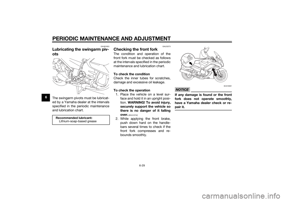
Checkin g the front forkThe condition and operation of the
front fork must be checked as follows
at the intervals specified in the periodic
maintenance and lubrication chart.
To check the con dition
Check the inner tubes for scratches,
damage and excessive oil leakage.
To check the operation 1. Place the vehicle on a level sur- face and hold it in an upright posi-
tion. WARNING! To avoi d injury,
securely support the vehicle so
there is no dan ger of it fallin g
over.
[EWA10752]
2. While applying the front brake, push down hard on the handle-
bars several times to check if the
front fork compresses and re-
bounds smoothly.
NOTICE
ECA10591
If any d amage is foun d or the front
fork does not operate smoothly,
have a Yamaha dealer check or re-
pair it.
Recommen ded lu bricant:
Lithium-soap-based grease
U1MCE2E0.book Page 29 Monday, June 16, 2014 8:57 AM
Page 97 of 120

PERIODIC MAINTENANCE AND ADJUSTMENT
6-30
6
EAU45512
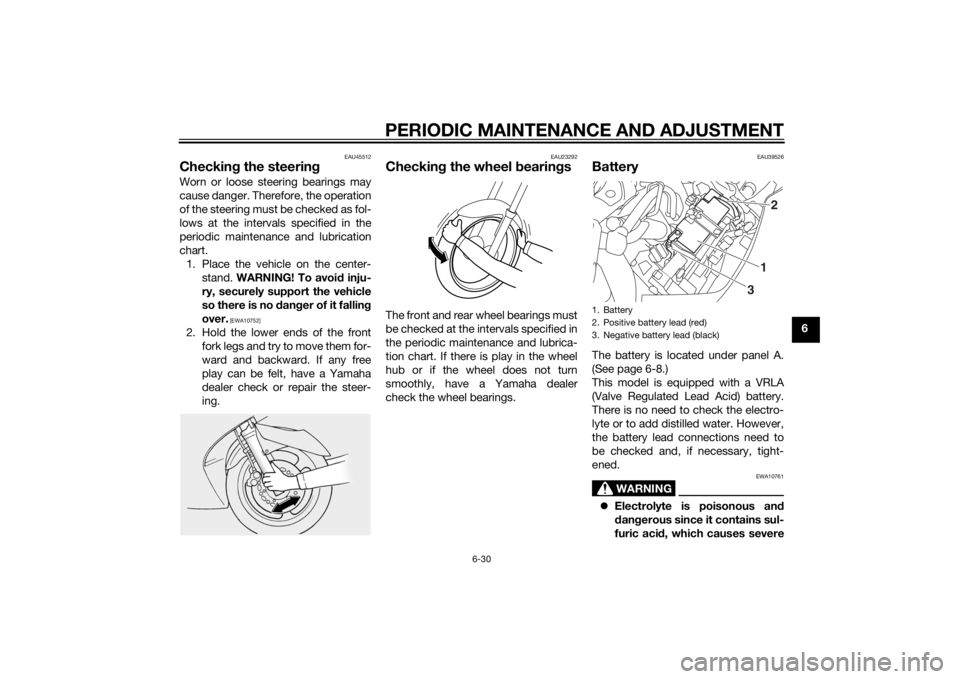
Checking the steerin gWorn or loose steering bearings may
cause danger. Therefore, the operation
of the steering must be checked as fol-
lows at the intervals specified in the
periodic maintenance and lubrication
chart.
1. Place the vehicle on the center- stand. WARNING! To avoi d inju-
ry, securely support the vehicle
so there is no d anger of it fallin g
over.
[EWA10752]
2. Hold the lower ends of the front fork legs and try to move them for-
ward and backward. If any free
play can be felt, have a Yamaha
dealer check or repair the steer-
ing.
EAU23292
Checkin g the wheel bearin gsThe front and rear wheel bearings must
be checked at the intervals specified in
the periodic maintenance and lubrica-
tion chart. If there is play in the wheel
hub or if the wheel does not turn
smoothly, have a Yamaha dealer
check the wheel bearings.
EAU39526
BatteryThe battery is located under panel A.
(See page 6-8.)
This model is equipped with a VRLA
(Valve Regulated Lead Acid) battery.
There is no need to check the electro-
lyte or to add distilled water. However,
the battery lead connections need to
be checked and, if necessary, tight-
ened.
WARNING
EWA10761
Electrolyte is poisonous an d
d an gerous since it contains sul-
furic aci d, which causes severe1. Battery
2. Positive battery lead (red)
3. Negative battery lead (black)
1 2
3
U1MCE2E0.book Page 30 Monday, June 16, 2014 8:57 AM
Page 107 of 120

MOTORCYCLE CARE AND STORAGE7-2
7
off any
deter gent resi due usin g
plenty of water, as it is harmful
to plastic parts.
Do not use any harsh chemical
prod ucts on plastic parts. Be
sure to avoi d usin g cloths or
spon ges which have b een in
contact with stron g or a brasive
cleanin g prod ucts, solvent or
thinner, fuel ( gasoline), rust re-
movers or inhi bitors, brake flui d,
antifreeze or electrolyte.
Do not use hi gh-pressure wash-
ers or steam-jet cleaners since
they cause water seepag e and
d eterioration in the followin g ar-
eas: seals (of wheel an d swin g-
arm bearin gs, fork an d b rakes),
electric components (couplers,
connectors, instruments,
switches an d li ghts), breather
hoses an d vents.
For motorcycles equippe d with
a win dshiel d: Do not use stron g
cleaners or har d spon ges as
they will cause dullin g or
sc r
atchin g. Some cleanin g
compoun ds for plastic may
leave scratches on the win d- shiel
d. Test the pro duct on a
small hi dden part of the win d-
shiel d to make sure that it does
not leave any marks. If the win d-
shiel d is scratche d, use a quality
plastic polishin g compoun d af-
ter washing .
After normal useRemove dirt with warm water, a mild
detergent, and a soft, clean sponge,
and then rinse thoroughly with clean
water. Use a toothbrush or bottlebrush
for hard-to-reach areas. Stubborn dirt
and insects will come off more easily if
the area is covered with a wet cloth for
a few minutes before cleaning.
After riding in the rain, near the sea oron salt-sprayed roadsSince sea salt or salt sprayed on roads
during winter are extremely corrosive
in combination with water, carry out
the following steps after each ride in
the rain, near the sea or on salt-
sprayed roads.
TIPSalt sprayed on roads in the winter
may remain well into spring.1. Clean the motorcycle with cold
water and a mild detergent, after
the engine has cooled down.
NOTICE: Do not use warm wa-
ter since it increases the corro-
sive action of the salt.
[ECA10792]
2. After drying the motorcycle, apply a corrosion protection spray on all
metal, including chrome- and
nickel-plated, surfaces to prevent
corrosion.
Windshield cleaningAvoid using any alkaline or strong acid
cleaner, gasoline, brake fluid, or any
other solvent. Clean the windshield
with a cloth or sponge dampened with
a neutral detergent, and after cleaning,
thoroughly wash it off with water. For
additional cleaning, use Yamaha Wind-
shield Cleaner or other quality cleaner.
Some cleaning compounds for plastics
may leave scratches on surfaces of the
U1MCE2E0.book Page 2 Monday, June 16, 2014 8:57 AM
Page 112 of 120

SPECIFICATIONS
8-2
8
Secondary reduction ratio:2.698 (35/37 x 21/27 x 33/9)
Transmission type: Constant mesh 5-speed
Operation:
Left foot operation
Gear ratio: 1st:
2.529 (43/17)
2nd: 1.773 (39/22)
3rd: 1.348 (31/23)
4th:
1.077 (28/26)
5th: 0.929 (26/28)Chassis:Frame type:
Diamond
Caster angle: 26.00 °
Trail: 109 mm (4.3 in)Front tire:Type:Tubeless
Size: 120/70 ZR17M/C (58W)
Manufacturer/model:
BRIDGESTONE/BT023F F
Manufacturer/model: METZELER/Roadtec Z8
Rear tire:Type:Tubeless
Size:
180/55 ZR17M/C (73W)
Manufacturer/model: BRIDGESTONE/BT023R F
Manufacturer/model: METZELER/Roadtec Z8 CLoa din g:Maximum load:
215 kg (474 lb)
(Total weight of rider, passenger, cargo
and accessories)Tire air pressure (measure d on col d
tires):Loading condition:
0–90 kg (0–198 lb)
Front:
250 kPa (2.50 kgf/cm², 36 psi)
Rear: 290 kPa (2.90 kgf/cm², 42 psi)
Loading condition: 90–215 kg (198–474 lb)
Front:
250 kPa (2.50 kgf/cm², 36 psi)
Rear: 290 kPa (2.90 kgf/cm², 42 psi)
High-speed riding: Front: 250 kPa (2.50 kgf/cm², 36 psi)
Rear: 290 kPa (2.90 kgf/cm², 42 psi)
Front wheel:Wheel type:Cast wheel
Rim size:
17M/C x MT3.50Rear wheel:Wheel type:Cast wheel
Rim size:
17M/C x MT5.50Unifie d b rake system:Operation:
Activated by rear brakeFront brake:Type:
Dual disc brake
Operation: Right hand operation
Specified brake fluid:
DOT 4Rear brake:Type:
Single disc brake
Operation:
Right foot operation
Specified brake fluid: DOT 4Front suspension:Type:
Telescopic fork
Spring/shock absorber type: Coil spring/oil damper
Wheel travel: 135 mm (5.3 in)
U1MCE2E0.book Page 2 Monday, June 16, 2014 8:57 AM
Page 116 of 120

10-1
10
INDEXAABS ....................................................... 3-27
ABS warning light ................................... 3-5
Accessory box ...................................... 3-36
Air filter element, cleaning .................... 6-17
Auxiliary DC jack ................................... 3-45
Auxiliary light......................................... 6-34BBattery .................................................. 6-30
Brake and clutch fluid levels, checking ............................................. 6-24
Brake and clutch fluids, changing ........ 6-25
Brake and clutch levers, checking and lubricating ........................................... 6-27
Brake and shift pedals, checking and
lubricating ........................................... 6-26
Brake lever ............................................ 3-26
Brake lever free play, checking............. 6-22
Brake light switches.............................. 6-23
Brake pedal........................................... 3-26CCables, checking and lubricating ......... 6-26
Care ........................................................ 7-1
Catalytic converters .............................. 3-31
Centerstand and sidestand, checking and lubricating .................................... 6-28
Clutch lever ................................. 3-25, 6-22
Coolant ................................................. 6-16
Cowling vents, opening and closing ..... 3-37
Cruise control indicator lights ................. 3-4
Cruise control switches ........................ 3-24
Cruise control system ............................. 3-6DDimmer/Pass switch ............................. 3-24 D-mode (drive mode) ........................... 3-23
EEngine break-in ...................................... 5-3
Engine idling speed, checking ............. 6-18
Engine oil and oil filter
cartridge ........... 6-12
Engine serial number .............................. 9-1
Engine trouble warning light ................... 3-5FFinal gear oil ......................................... 6-14
Front and rear brake pads, checking ... 6-23
Front fork, adjusting ............................. 3-39
Front fork, checking ............................. 6-29
Front turn signal light............................ 6-34
Fuel ....................................................... 3-30
Fuel consumption, tips for reducing ...... 5-3
Fuel tank breather/overflow hose ......... 3-31
Fuel tank cap ........................................ 3-29
Fuses, replacing ................................... 6-32HHandlebar position, adjusting .............. 3-37
Handlebar switches .............................. 3-23
Hazard switch....................................... 3-24
Headlight beams, adjusting.................. 3-37
Headlight bulb ...................................... 6-33
High beam indicator light ....................... 3-4
Horn switch .......................................... 3-24IIdentification numbers ............................ 9-1
Ignition circuit cut-off system ............... 3-43
Immobilizer system ................................ 3-1
Immobilizer system indicator light .......... 3-6
Indicator lights and warning lights ......... 3-4LLicense plate light bulb, replacing........ 6-35
MMain switch/steering lock .......................3-2
Maintenance and lubrication, periodic....6-4
Maintenance, emission control
system ..................................................6-3
Matte color, caution ................................7-1
Menu switch..........................................3-24
Model label .............................................9-1
Multi-function meter unit .......................3-10NNeutral indicator light ..............................3-4OOil level warning light ..............................3-4PPanels, removing and installing ..............6-8
Parking ....................................................5-4
Part locations ..........................................2-1RRear suspension, lubricating ................6-28
Rear view mirrors ..................................3-39
Rider seat height, adjusting ..................3-33SSafety information ...................................1-1
Seats .....................................................3-32
Select switch.........................................3-25
Shifting ....................................................5-2
Shift pedal .............................................3-26
Shock absorber assembly, adjusting ....3-41
Sidestand ..............................................3-42
Spark plugs, checking ..........................6-11
Specifications .........................................8-1
Start/Engine stop switch .......................3-24
Starting the engine ..................................5-1
Steering, checking ................................6-30
U1MCE2E0.book Page 1 Monday, June 16, 2014 8:57 AM