2015 VOLVO V60 transmission
[x] Cancel search: transmissionPage 5 of 414

Contents
* Option/accessory, for more information, see Introduction.3
03
03 Your driving environment
Instruments and controls.......................... 80
Ignition modes.......................................... 90
Seats......................................................... 92
Steering wheel.......................................... 99
Lighting................................................... 101
Wipers and washers............................... 109
Windows................................................. 112
Mirrors..................................................... 114
Digial compass*...................................... 117
Power moonroof* ................................... 119 HomeLink ®
Wireless Control System*.... 121
Starting the engine.................................. 124
Transmission........................................... 129
Eco Guide* and Power Meter*................ 134
Eco* ........................................................ 136
Start/Stop* ............................................. 139
Brakes..................................................... 143
Parking brake.......................................... 146
04
04 Driver support
Stability system....................................... 152
Road sign information (RSI)* .................. 155
Cruise control.......................................... 157
Adaptive Cruise Control (ACC)*.............. 159
Distance Alert* ....................................... 170
City Safety™ .......................................... 173Pedestrian and Cyclist Detection with
Full Auto Brake*...................................... 179
Driver Alert System* ............................... 189
Park assist*............................................. 198
Rear Park Assist Camera (PAC)* ............ 202
Park Assist Pilot (PAP)* .......................... 206
Blind Spot Information System (BLIS)* .. 210
05
05 Comfort and driving pleasure
Volvo Sensus.......................................... 216
Menus and messages............................. 217
The MY CAR menus............................... 219
Climate system....................................... 225
Trip computer......................................... 234
Active chassis system–Four C*............... 241
Passenger compartment convenience... 242
Page 65 of 414

02 Locks and alarm
Remote key and key blade
02
}}
* Option/accessory, for more information, see Introduction.63
Unique functions—PCC*
Information button
Indicator lights
Pressing the information button provides cer- tain information about the vehicle with thehelp of the indicator lights.
Using the information button1. Press the information button .
2. All of the indicator lights will flash sequentially for approximately 7 seconds to indicate that the PCC is receiving infor-mation from the vehicle. If any of the but-tons are pressed during this 7-secondperiod, transmission of information to thePCC will be interrupted.
NOTE
If none of the indicator lights flash when the information button has been pressedseveral times from different places in rela-tion to the vehicle, contact an authorizedVolvo service technician.
The indicator lights provide information according to the illustration:
Steady green light: the vehicle is correctly locked.
Steady yellow light: the vehicle is not locked.
Steady red light: the alarm has been trig- gered since the vehicle was most recentlylocked.
Both red lights flash alternatively: the alarm was triggered less than 5 minutesago.
RangeThe PCC's lock and unlock functions have arange of approximately 60 ft. (20 m) from thevehicle.
NOTE
•The approach lighting, panic alarm, and the functions controlled by theinformation button have a range ofapproximately 300 ft (100 m) from thevehicle.
• Radio waves, buildings or other obsta-cles may interfere with the function ofthe PCC.
If the vehicle does not provide confirmation when a button has been pressed, try movingcloser and pressing the button again.
Outside of the PCC´s rangeIf the PCC is more than approximately 300 ft (100 m) from the vehicle when the informationbutton is pressed, no new information will bereceived. The PCC most recently used to lock
Page 66 of 414

02 Locks and alarm
Remote key and key blade
02
64
or unlock the vehicle will show the vehicle's most recently received status. The indicatorlights will not flash when the information but-ton is pressed while the PCC is out of range. If more than one PCC is used to lock/unlock the vehicle, only the one used most recentlywill show the correct locking status.
NOTE
If none of the indicator lights illuminate when the information button is pressed,this may be because the most recenttransmission between the vehicle and thePCC was interrupted or impeded by build-ings or other objects.
Keyless driveVehicles equipped with the optional Personal Car Communicator have the keyless drivefunction, see page 68 for detailed informa-tion.
Detachable key blade
The key blade can be removed from the remote key. When removed, the key bladecan be used to:• Lock/unlock the driver's door if the remote key is not functioning properly
• Lock/unlock the glove compartment (seepage 73)
• Override the transmission's shiftlock sys-tem (see page 132)
• Enable/disable the private locking func-tion (see page 67)
• The front passenger's door and the rearside doors can be locked manually if nec-essary (see page 71)
Removing the key blade
Slide the spring loaded catch to the side.
Pull the key blade straight out of the remote key.
Reinserting the key blade in the remote key
1. Hold the remote key with the slot for the
key blade up.
2. Carefully slide the key blade into its groove.
3. Gently press the key blade in the groove until it clicks into place.
Page 80 of 414

78* Option/accessory, for more information, see Introduction. Instruments and controls........................................................................ 80 Ignition modes........................................................................................ 90Seats....................................................................................................... 92Steering wheel........................................................................................ 99Lighting................................................................................................. 101
Wipers and washers.............................................................................. 109Windows............................................................................................... 112Mirrors................................................................................................... 114
Digial compass*.................................................................................... 117
Power moonroof* ................................................................................. 119 HomeLink
®
Wireless Control System*.................................................. 121
Starting the engine................................................................................ 124 Transmission......................................................................................... 129
Eco Guide* and Power Meter*.............................................................. 134Eco* ...................................................................................................... 136Start/Stop* ........................................................................................... 139Brakes................................................................................................... 143Parking brake........................................................................................ 146
Page 86 of 414

03 Your driving environment
Instruments and controls
03
84* Option/accessory, for more information, see Introduction.
Indicator and warning symbols: digital instrument panel
Indicator symbols
Indicator and warning symbols
Warning symbols
Function checkAll indicator and warning symbols light up in ignition mode II or when the engine is started.
When the engine has started, all the symbolsshould go out except the parking brake sym-bol, which only goes out when the brake isdisengaged. If the engine does not start or if the function check is carried out in ignition mode II, all
symbols go out after 5 seconds except themalfunction indicator light, which may indi- cate a fault in the vehicle's emissions system,and the symbol for low oil pressure. Some of the symbols shown may not be available in all markets or models.
Indicator symbols
SymbolDescription
Fault in the Active Bending Light (ABL)*system
Malfunction indicator light
Anti-lock brake system (ABS)
Rear fog lights on
Stability system
The stability system's Sport mode is activated
Low fuel level
Information symbol, read the text displayed in the instrumentpanel
High beam indicator
SymbolDescription
Left turn signal indicator
Right turn signal indicator
Tire pressure monitoring sensor (TPMS)
A
A
Option in Canada
Fault in the Active Bending Light
(ABL) system
This symbol will illuminate if there is a fault in the ABL system. See page 104 for moreinformation about this system.
Malfunction Indicator Light
As you drive, a computer called On-Board Diagnostics II (OBDII) monitors your vehicle'sengine, transmission, electrical and emissionsystems. The malfunction indicator light will illuminate if the computer senses a condition that poten-tially may need correcting. When this hap-pens, please have your vehicle checked by atrained and qualified Volvo service technicianas soon as possible. A malfunction indicator light may have many causes. Sometimes, you may not notice a
Page 100 of 414

03 Your driving environment
Seats
03
98
WARNING
•When one or more sections of the backrest is returned to the uprightposition, check that it is properlylocked in place by pushing and pullingit. The red indicators should also notbe visible.
• Return the outboard head restraints tothe upright position.
• Long loads should always be securelyanchored to help avoid injury in theevent of a sudden stop.
• Always turn the engine off and applythe parking brake when loading/unloading the vehicle.
• Place the transmission in the Park (
P)
position to help prevent inadvertentmovement of the gear selector.
• On hot days, the temperature in thevehicle interior can rise very quickly.Exposure of people to these high tem-peratures for even a short period oftime can cause heat-related injury ordeath. Small children are particularly atrisk.
Page 117 of 414

03 Your driving environment
Mirrors
03
}}
* Option/accessory, for more information, see Introduction.115
Automatically tilting the door mirrors when parking
The door mirrors can tilt down automatically to help give the driver a better view along thesides of the vehicle, for example when paral-lel parking. When the transmission is nolonger in reverse, the mirrors will automati-cally return to their original position. This function can be activated/deactivated in MY CAR under
SettingsCar settings
Side mirror settingsIn reverse gear tilt
left mirror
or In reverse gear tilt right
mirror. See page 219 for information about
the MY CAR menu system.
Automatic retraction when lockingWhen the vehicle is locked/unlocked with the remote key the door mirrors are automaticallyretracted/extended. The function can be activated/deactivated in MY CAR under
SettingsCar settings
Side mirror settingsRetract side mirrors
when locking. See page 219 for a descrip-
tion of the menu system.
Resetting to neutralMirrors that have been moved out of position by an external force must be electrically reset to the neutral position for electric retracting/extending to work. •
Retract the mirrors with the
L and R but-
tons.
• Fold them out again with the
L and R but-
tons.
The mirrors are now reset in neutral position.
Home safe and approach lightingThe light on the door mirrors comes on when approach lighting or home safe lighting isselected, see page 108.
Heated windshield*, rear window and door mirror defrosters
Max. defroster/heated windshield (1), rear win- dow and door mirror defroster (2) Press button (1) to defrost/de-ice the wind- shield and/or button (2) to defrost the rearwindow and door mirrors. The indicator lightsin the respective buttons indicate that thefunction is active. Switch the function offwhen then windshield/rear window/mirrorshave cleared to help avoid battery drain.Theheating function will also switch off automati-cally after a certain amount of time. Auto-defrosting for the rear window and door mirrors (if the vehicle is started when theambient temperature is below 45 °F (7 °C)can be selected in
MY CAR under
Settings
Climate settingsAutomatic rear
defroster. See page 219 for a description of
the menu system.
Interior rearview mirror
Auto-dim functionThe interior rearview mirror’s auto-dim func- tion is controlled by two sensors: one point-ing forward (located on the forward-facingside of the mirror, which monitors the amountof ambient light) and one pointing rearward(located on the side of the mirror facing thedriver at the upper edge, which senses thestrength of following vehicles' headlights), and work together to help eliminate glare. 1
1
The auto-dim function is also available as an option on the door mirrors.
Page 123 of 414

03 Your driving environment
HomeLink®
Wireless Control System*
03
}}
* Option/accessory, for more information, see Introduction.121
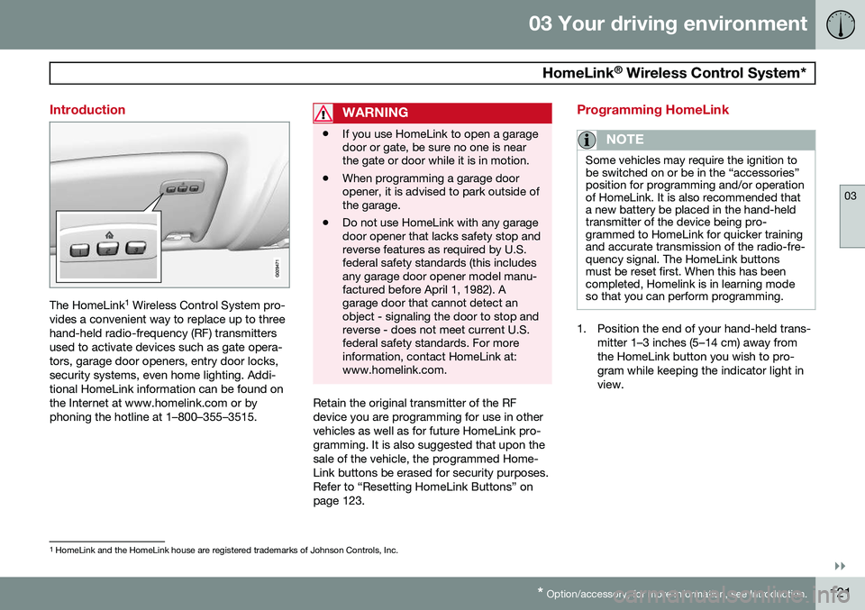
Introduction
The HomeLink 1
Wireless Control System pro-
vides a convenient way to replace up to three hand-held radio-frequency (RF) transmittersused to activate devices such as gate opera-tors, garage door openers, entry door locks,security systems, even home lighting. Addi-tional HomeLink information can be found onthe Internet at www.homelink.com or byphoning the hotline at 1–800–355–3515.
WARNING
• If you use HomeLink to open a garage door or gate, be sure no one is nearthe gate or door while it is in motion.
• When programming a garage dooropener, it is advised to park outside ofthe garage.
• Do not use HomeLink with any garagedoor opener that lacks safety stop andreverse features as required by U.S.federal safety standards (this includesany garage door opener model manu-factured before April 1, 1982). Agarage door that cannot detect anobject - signaling the door to stop andreverse - does not meet current U.S.federal safety standards. For moreinformation, contact HomeLink at:www.homelink.com.
Retain the original transmitter of the RF device you are programming for use in othervehicles as well as for future HomeLink pro-gramming. It is also suggested that upon thesale of the vehicle, the programmed Home-Link buttons be erased for security purposes.Refer to “Resetting HomeLink Buttons” onpage 123.
Programming HomeLink
NOTE
Some vehicles may require the ignition to be switched on or be in the “accessories”position for programming and/or operationof HomeLink. It is also recommended thata new battery be placed in the hand-heldtransmitter of the device being pro-grammed to HomeLink for quicker trainingand accurate transmission of the radio-fre-quency signal. The HomeLink buttonsmust be reset first. When this has beencompleted, Homelink is in learning modeso that you can perform programming.
1. Position the end of your hand-held trans-
mitter 1–3 inches (5–14 cm) away from the HomeLink button you wish to pro-gram while keeping the indicator light inview.
1HomeLink and the HomeLink house are registered trademarks of Johnson Controls, Inc.