2015 VOLVO V60 tire pressure
[x] Cancel search: tire pressurePage 320 of 414
08 Wheels and tires
Tire inflation
08
318
After driving a distance of approximately
1 mile (1.6 km), the tires are considered to behot. If you have to drive farther than this dis-tance to pump your tire(s), check and recordthe tire pressure first and add the appropriateair pressure when you get to the pump. If checking tire pressure when the tire is hot, never "bleed" or reduce air pressure. Thetires are hot from driving and it is normal forpressures to increase above recommendedcold pressures. A hot tire at or below recom-mended cold inflation pressure could be sig-nificantly under-inflated.
To check inflation pressure:1. Remove the cap from the valve on onetire, then firmly press the tire gauge onto the valve.
2. Add air to reach the recommended air pressure. 3. Replace the valve cap.
CAUTION
•
After pumping the tires, always reinstall the valve cap to help avoid damage tothe valve from dirt, gravel, etc.
• Use plastic valve caps only. Metal capscould corrode and become difficult toremove.
4. Visually inspect the tires to make sure
there are no nails or other objects embedded that could puncture the tireand cause an air leak.
5. Check the sidewalls to make sure there are no gouges, cuts, bulges or otherirregularities.
6. Repeat this procedure for each tire, including the spare 2
.
NOTE
• If you overfill the tire, release air by pushing on the metal stem in the cen-ter of the valve. Then recheck thepressure with your tire gauge.
• Some spare tires (available as anaccessory) require higher inflationpressure than the other tires. Consultthe tire inflation pressure table on page320 or see the inflation pressure plac-ard.
Tire ratings
Speed ratingsThe speed ratings in the table translate as fol- low:
Speed ratings
M81 mph (130 km/h)
Q100 mph (160 km/h)
T118 mph (190 km/h)
H130 mph (210 km/h)
V149 mph (240 km/h)
2
Available as an accessory
Page 322 of 414
08 Wheels and tires
Inflation pressure
08
320
Tire inflation pressure table
The following tire pressures are recommended by Volvo for your vehicle. Refer to the tire inflation placard (see page 317 for its location) for informa- tion specific to the tires installed on your vehicle at the factory.
Tire sizeCold tire pressure for up to five persons
Front psi (kPa)Rear psi (kPa)
235/45 R17 Extra load 235/45 R17 SST Extra loadA36 (250)36 (250)
215/50 R17 Extra load 235/40 R18 Extra load235/45 R18 Extra load235/40 R19 Extra load38 (260)38 (260)
Temporary spare tireB
T125/80R1761 (420)61 (420)
A Run-flat tire
B Available as an accessory
Page 323 of 414
08 Wheels and tires
Inflation pressure
08
321
WARNING
19” wheels may never be used on vehicles
that are not equipped with the R-design or
the Sport chassis options. Using 19” wheels on vehicles equipped the standard chassis presents a safety
risk and the risk of damage to the vehicle,and impairs the vehicle’s driving characte-ristics.
NOTE
Please consult a Volvo retailer’s Parts department for the most up-to-date speci-fications.
Page 324 of 414

08 Wheels and tires
Tire designations
08
322
Information on the sidewall
310
11
12
4
56789
2
1
G010753
Federal law mandates that tire manufacturers place standardized information on the side-wall of all tires (see the illustration). The following information is listed on the tire sidewall: The tire designation:
NOTE
Please be aware that the following tire designation is an example only and that
this particular tire may not be available onyour vehicle.
1. 215: the width of the tire (in millimeters)
from sidewall edge to sidewall edge. The larger the number, the wider the tire.
2. 65: The ratio of the tire's height to its
width in percent.
3. R: Radial tire (the designation RF and the
symbol indicate that the vehicle is
equipped with optional self-supporting run flat tires 1
. See page 342 for more
information about these tires).
4. 15: The diameter of the wheel rim (in
inches).
5. 95: The tire's load index. In this example,
a load index of 95 equals a maximum load of 1521 lbs (690 kg).
6. H: The tire's speed rating, or the maxi-
mum speed at which the tire is designedto be driven for extended periods of time,carrying a permissible load for the vehi-cle, and with correct inflation pressure.For example, H indicates a speed ratingof 130 mph (210 km/h).
NOTE
The tire's load index and speed rating may not appear on the sidewall because theyare not required by law.
7. M+S or M/S = Mud and Snow, AT = All
Terrain, AS = All Season
8. U.S. DOT Tire Identification Number (TIN)
: This begins with the letters "DOT"
and indicates that the tire meets all fed- eral standards. The next two numbers orletters are the plant code where it wasmanufactured, the next two are the tiresize code and the last four numbers rep-resent the week and year the tire wasbuilt. For example, 1510 means that thetire was manufactured during week 15 of2010. The numbers in between are mar-keting codes used at the manufacturer'sdiscretion. This information helps a tiremanufacturer identify a tire for safetyrecall purposes.
9. Tire Ply Composition and Material Used
: Indicates the number of plies indi-
cates or the number of layers of rubber- coated fabric in the tire tread and side-wall. Tire manufacturers also must indi-cate the ply materials in the tire and thesidewall, which include steel, nylon, poly-ester, and others.
1 Self-supporting run flat tires may not be available on all models
Page 325 of 414
08 Wheels and tires
Tire designations
08
323
10.
Maximum Load : Indicates the maximum
load in pounds and kilograms that can be carried by the tire. Refer to the vehicle'stire information placard located on the B-Pillar for the correct tire pressure for yourvehicle.
11. Treadwear, Traction, and Temperature grades
: see page 327 for more informa-
tion.
12. Maximum permissible inflationpressure:
the greatest amount of air
pressure that should ever be put in the tire. This limit is set by the tire manufac-turer.
Page 326 of 414
08 Wheels and tires
Glossary of tire terminology
08
324
Terms
The tire suppliers may have additional mark- ings, notes or warnings such as standardload, radial tubeless, etc.
• Tire information placard
: A placard
showing the OE (Original Equipment) tire sizes, recommended inflation pressure,and the maximum weight the vehicle cancarry.
• Tire Identification Number (TIN)
: A
number on the sidewall of each tire pro-viding information about the tire brandand manufacturing plant, tire size anddate of manufacturer.
• Inflation pressure
: A measure of the
amount of air in a tire.
• Standard load
: A class of P-metric or
Metric tires designed to carry a maximumload at 35 psi [37 psi (2.5 bar) for Metrictires]. Increasing the inflation pressurebeyond this pressure will not increase thetires load carrying capability.
• Extra load
: A class of P-metric or Metric
tires designed to carry a heavier maxi-mum load at 41 psi [43 psi (2.9 bar) forMetric tires]. Increasing the inflation pres-sure beyond this pressure will notincrease the tire's load carrying capabil-ity.
• kPa
: Kilopascal, a metric unit of air pres-
sure. •
PSI
: Pounds per square inch, a standard
unit of air pressure.
• B-pillar
: The structural member at the
side of the vehicle behind the front door.
• Bead area of the tire
: Area of the tire
next to the rim.
• Sidewall of the tire
: Area between the
bead area and the tread.
• Tread area of the tire
: Area of the perim-
eter of the tire that contacts the roadwhen mounted on the vehicle.
• Rim
: The metal support (wheel) for a tire
or a tire and tube assembly upon whichthe tire beads are seated.
• Maximum load rating
: a figure indicating
the maximum load in pounds and kilo-grams that can be carried by the tire. Thisrating is established by the tire manufac-turer.
• Maximum permissible inflation pressure
: the greatest amount of air
pressure that should ever be put in the tire. This limit is set by the tire manufac-turer.
• Recommended tire inflation pressure
:
inflation pressure, established by Volvo,which is based on the type of tires thatare mounted on a vehicle at the factory.This information can be found on the tireinflation placard(s) located on the driver's side B-pillar and in the tire inflation tablein this chapter.
• Cold tires
: The tires are considered to be
cold when they have the same tempera-ture as the surrounding (ambient) air. Thistemperature is normally reached after thevehicle has been parked for at least3 hours.
Page 332 of 414
08 Wheels and tires
Tire Sealing System*
08
330* Option/accessory, for more information, see Introduction.
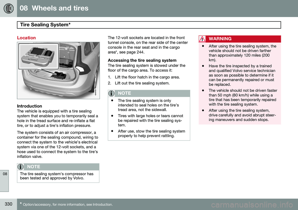
Location
IntroductionThe vehicle is equipped with a tire sealing system that enables you to temporarily seal ahole in the tread surface and re-inflate a flattire, or to adjust a tire’s inflation pressure. The system consists of an air compressor, a container for the sealing compound, wiring toconnect the system to the vehicle’s electricalsystem via one of the 12-volt sockets, and ahose used to connect the system to the tire’sinflation valve.
NOTE
The tire sealing system's compressor has been tested and approved by Volvo.
The 12-volt sockets are located in the front tunnel console, on the rear side of the centerconsole in the rear seat and in the cargoarea*, see page 244.
Accessing the tire sealing systemThe tire sealing system is stowed under thefloor of the cargo area. To access it:
1. Lift the floor hatch in the cargo area.
2. Lift out the tire sealing system.
NOTE
• The tire sealing system is only intended to seal holes on the tire’stread area, not the sidewall.
• Tires with large holes or tears cannotbe repaired with the tire sealing sys-tem.
• After use, stow the tire sealing systemproperly to help prevent rattling.
WARNING
• After using the tire sealing system, the vehicle should not be driven fartherthan approximately 120 miles (200km).
• Have the tire inspected by a trainedand qualified Volvo service technicianas soon as possible to determine if itcan be permanently repaired or mustbe replaced.
• The vehicle should not be driven fasterthan 50 mph (80 km/h) while using atire that has been temporarily repairedwith the tire sealing system.
• After using the tire sealing system,drive carefully and avoid abrupt steer-ing maneuvers and sudden stops.
Page 333 of 414
08 Wheels and tires
Tire Sealing System*
08
}}
* Option/accessory, for more information, see Introduction.331
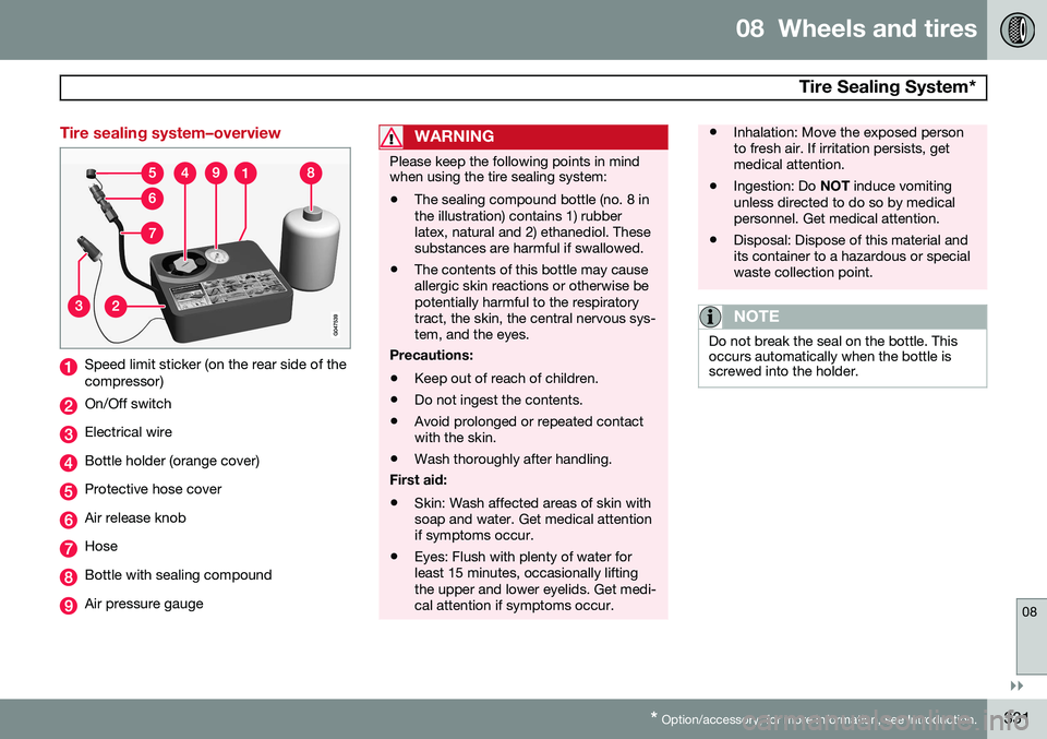
Tire sealing system–overview
Speed limit sticker (on the rear side of the compressor)
On/Off switch
Electrical wire
Bottle holder (orange cover)
Protective hose cover
Air release knob
Hose
Bottle with sealing compound
Air pressure gauge
WARNING
Please keep the following points in mind when using the tire sealing system:
• The sealing compound bottle (no. 8 in the illustration) contains 1) rubberlatex, natural and 2) ethanediol. Thesesubstances are harmful if swallowed.
• The contents of this bottle may causeallergic skin reactions or otherwise bepotentially harmful to the respiratorytract, the skin, the central nervous sys-tem, and the eyes.
Precautions: • Keep out of reach of children.
• Do not ingest the contents.
• Avoid prolonged or repeated contact with the skin.
• Wash thoroughly after handling.
First aid:
• Skin: Wash affected areas of skin withsoap and water. Get medical attentionif symptoms occur.
• Eyes: Flush with plenty of water forleast 15 minutes, occasionally liftingthe upper and lower eyelids. Get medi-cal attention if symptoms occur.
• Inhalation: Move the exposed person to fresh air. If irritation persists, getmedical attention.
• Ingestion: Do
NOT induce vomiting
unless directed to do so by medicalpersonnel. Get medical attention.
• Disposal: Dispose of this material andits container to a hazardous or specialwaste collection point.
NOTE
Do not break the seal on the bottle. This occurs automatically when the bottle isscrewed into the holder.