Page 191 of 211

Find a firm and level surface suitable for lifting the vehicle.
Stop the engine, select a gear on a manual gearbox or with an automated manual
gearbox, move the selector lever to D or R with the ignition switched onChanging gear
then apply the handbrake firmly Braking, stopping and parking.
Chock the wheel diagonally opposite using the collapsible chocks or other suitable objects.
Loosen the wheel bolts on the wheel that is being changed Wheel bolts.
Find the jacking point under the vehicle which is closest to the wheel that is being
changed.
Raise the vehicle jack until it just fits under the jacking point of the vehicle.
Ensure that the foot of the jack is resting securely on the ground with its whole surface and
that the foot of the jack is positioned precisely, i.e. vertically beneath the point of
application .
Position the vehicle jack. At the same time, continue to crank the claw up until it is in
position around the vertical rib underneath the vehicle .
Lifting the vehicle with the jack
Fig. 154 Jacking points for the vehicle jack (mirrored on the right-hand side of the vehicleyf
Fig. 155 Vehicle jack at the rear left-hand side of the vehicle
First read and observe the introductoryinformation and safety warnings⇒
Introduction
The jack may be applied only at the jacking points shown (markings on the bodyyf� ⇒ Fig. 154.
Always use the jacking point closest to the wheel you are working on ⇒.
Raise the vehicle using only the designated jacking points.
Checklist
To ensure your own safety and that of your passengers, observe the following actions in the
specified order ⇒:
Incorrectly tightened wheel bolts can loosen while the vehicle is in motion and cause
accidents, serious injury, and loss of control of the vehicle.
\f
Page 192 of 211
Crank the vehicle jack further until the wheel is just clear of the ground.
Changing a wheel
Fig. 156 Changing a wheel: removing the wheel bolts with the screwdriver handle
First read and observe the introductoryinformation and safety warnings⇒
Introduction
Removing the wheel
\f
Page 193 of 211
After changing a wheel
First read and observe the introductoryinformation and safety warnings⇒
Introduction
\f
Page 194 of 211
Dispose of used or out-of-date sealant in accordance with legal requirements.
You can get a new tyre filler bottle from a Volkswagen dealership.
Observe the separate instructions from the manufacturer of the breakdown set.
Contents of the breakdown set
Fig. 157 The breakdown set
First read and observe the introductoryinformation and safety warnings⇒
Introduction
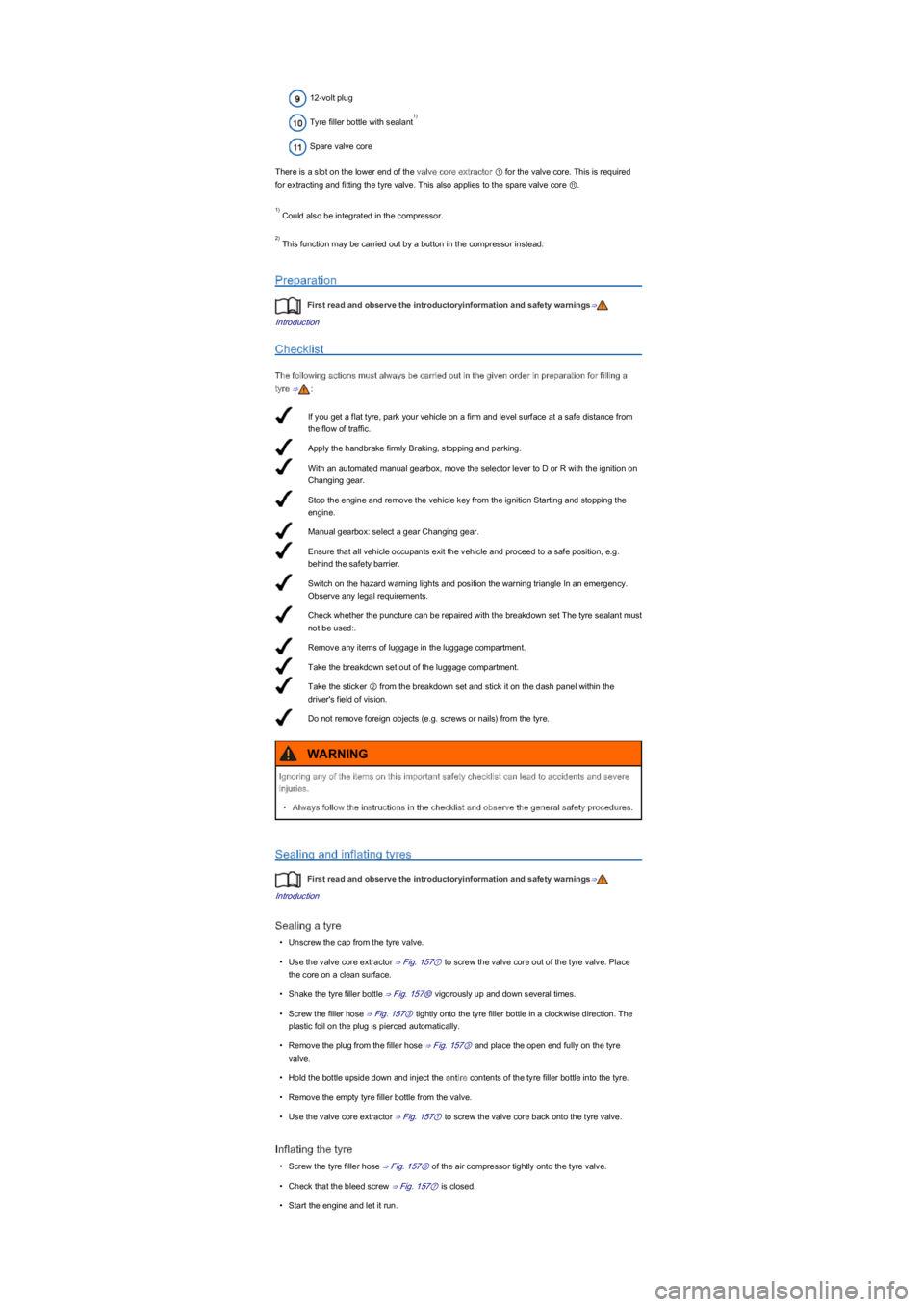
The breakdown set may be located underneath the floor covering in the luggage compartment. It
includes the following components ⇒ Fig. 157:
Valve core extractor
Sticker with the maximum permitted speed max. 80 km/h or max. 50 mph
Filler hose with plug
Air compressor
Tyre filler hose
Tyre pressure display
Air bleed screw
ON and OFF switch
Using the breakdown set can be dangerous, especially if the tyres are inflated at the roadside.
Please note the following steps in order to reduce the risk of serious injuries:
\f
Page 195 of 211

If you get a flat tyre, park your vehicle on a firm and level surface at a safe distance from
the flow of traffic.
Apply the handbrake firmly Braking, stopping and parking.
With an automated manual gearbox, move the selector lever to D or R with the ignition on
Changing gear.
Stop the engine and remove the vehicle key from the ignition Starting and stopping the
engine.
Manual gearbox: select a gear Changing gear.
Ensure that all vehicle occupants exit the vehicle and proceed to a safe position, e.g.
behind the safety barrier.
Switch on the hazard warning lights and position the warning triangle In an emergency.
Observe any legal requirements.
Check whether the puncture can be repaired with the breakdown set The tyre sealant must
not be used:.
Remove any items of luggage in the luggage compartment.
Take the breakdown set out of the luggage compartment.
Take the sticker ② from the breakdown set and stick it on the dash panel within the
driver's field of vision.
Do not remove foreign objects (e.g. screws or nailsyf���I�U�R�P���W�K�H���W�\�U�H�.
12-volt plug
Tyre filler bottle with sealant
Spare valve core
There is a slot on the lower end of the valve core extractor ① for the valve core. This is required
for extracting and fitting the tyre valve. This also applies to the spare valve core ⑪.
Could also be integrated in the compressor.
This function may be carried out by a button in the compressor instead.
Preparation
First read and observe the introductoryinformation and safety warnings⇒
Introduction
Checklist
The following actions must always be carried out in the given order in preparation for filling a
tyre ⇒:
Sealing and inflating tyres
First read and observe the introductoryinformation and safety warnings⇒
Introduction
Sealing a tyre
\f
Page 197 of 211
Several electrical consumers could share a single fuse. Conversely, a single consumer could have
more than one fuse.
Therefore fuses should only be replaced when the cause of the fault has been rectified. If a new
fuse blows shortly after insertion, have the electrical system checked by a qualified workshop as
soon as possible.
Additional information and warnings:
\f
Page 200 of 211

Park the vehicle on a firm and level surface at a safe distance from the flow of traffic.
Apply the handbrake firmly Braking, stopping and parking.
Turn the light switch to position 0 Lights.
Shift the turn signal lever to neutral Lights.
Automated manual gearbox: move the selector lever to D or R Changing gear.
Stop the engine and remove the vehicle key from the ignition Starting and stopping the
engine.
Manual gearbox: select a gear Changing gear.
Leave the defective bulbs to cool down.
Check to see if a fuse has blown Fuses.
Follow the instructions to change the affected bulb . Always use identical bulbs with the
same designation. The designation is inscribed on the bulb, either on the glass part or on
the base.
Do not touch the glass part of the bulb with unprotected fingers. The heat of the bulb would
cause the fingerprint to evaporate and condense on the reflector. This will impair the
brightness of the headlight.
After changing the bulb, check to ensure that the bulb is working properly. If the bulb is not
working properly, the bulb may not have been inserted properly or may have failed again,
or the connector may have been inserted incorrectly.
Any time you change a bulb in the front of the vehicle, the headlight settings should be
checked by a qualified workshop.
Information on changing bulbs
First read and observe the introductoryinformation and safety warnings⇒
Introduction
Checklist
Always carry out the following actions for changing a bulb in the given order ⇒:
Accidents can occur if roads are not sufficiently illuminated and other road users have
difficulty seeing the vehicle, or cannot see it at all.
WARNING
Changing the bulb incorrectly can cause accidents and serious injuries.
\f
Page 201 of 211

Changing bulbs in the front headlights
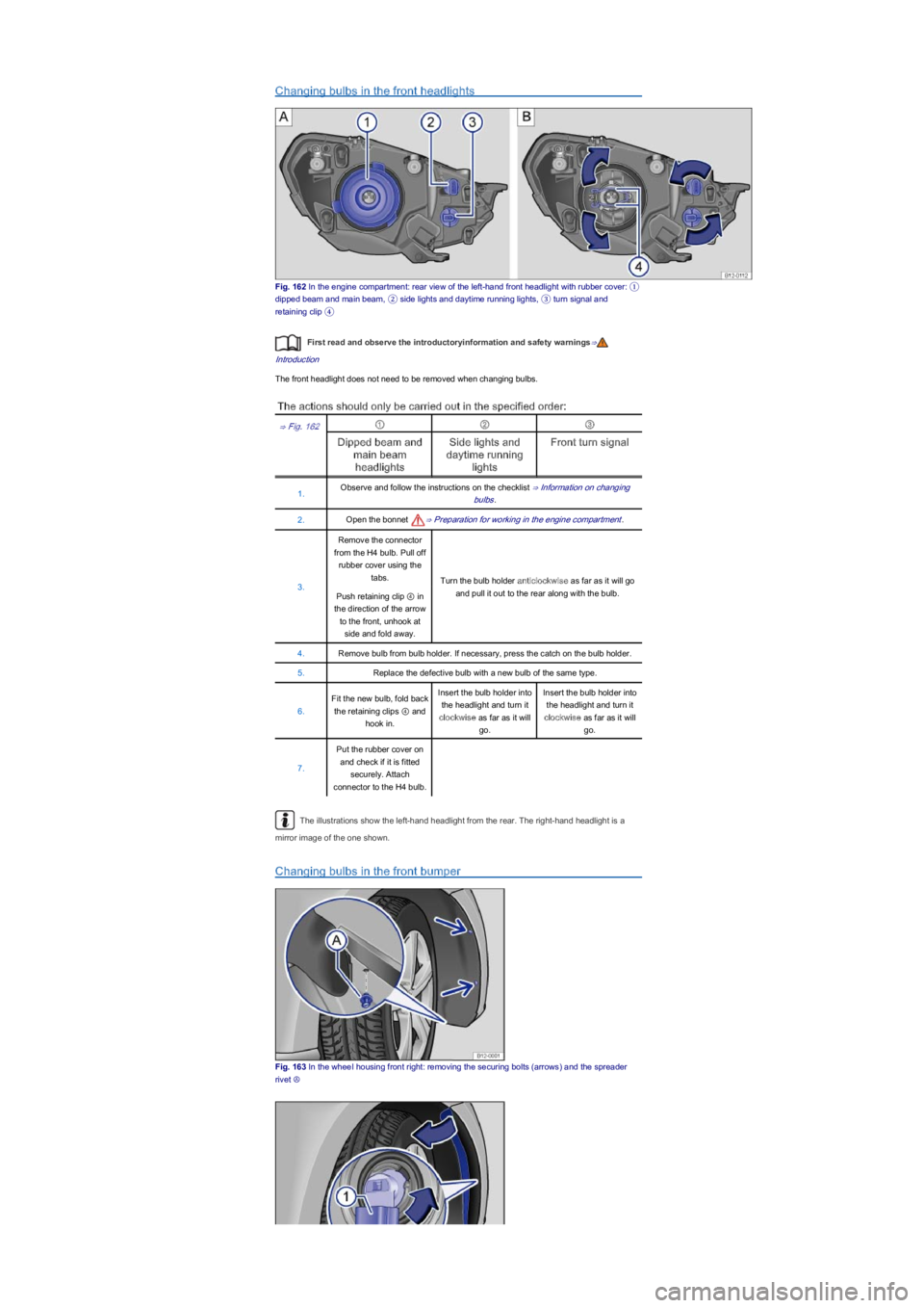
Fig. 162 In the engine compartment: rear view of the left-hand front headlight with rubber cover: ①
dipped beam and main beam, ② side lights and daytime running lights, ③ turn signal and
retaining clip �\b
First read and observe the introductoryinformation and safety warnings⇒
Introduction
The front headlight does not need to be removed when changing bulbs.
The actions should only be carried out in the specified order:
⇒ Fig. 162①②③
Dipped beam and
main beam
headlights
Side lights and
daytime running
lights
Front turn signal
1.Observe and follow the instructions on the checklist ⇒ Information on changing
bulbs.
2.Open the bonnet ⇒ Preparation for working in the engine compartment.
3.
Remove the connector
from the H4 bulb. Pull off
rubber cover using the
tabs.Turn the bulb holder anticlockwise as far as it will go
and pull it out to the rear along with the bulb.Push retaining clip ④ in
the direction of the arrow
to the front, unhook at
side and fold away.
4.Remove bulb from bulb holder. If necessary, press the catch on the bulb holder.
5.Replace the defective bulb with a new bulb of the same type.
6.
Fit the new bulb, fold back
the retaining clips ④ and
hook in.
Insert the bulb holder into
the headlight and turn it
clockwise as far as it will
go.
Insert the bulb holder into
the headlight and turn it
clockwise as far as it will
go.
7.
Put the rubber cover on
and check if it is fitted
securely. Attach
connector to the H4 bulb.
The illustrations show the left-hand headlight from the rear. The right-hand headlight is a
mirror image of the one shown.
Changing bulbs in the front bumper
Fig. 163 In the wheeI housing front right: removing the securing bolts (arrowsyf���D�Q�G���W�K�H���V�S�U�H�D�G�H�U�
rivet Ⓐ