2015 VAUXHALL ANTARA ignition
[x] Cancel search: ignitionPage 163 of 223

Vehicle care161
operation 3 times or more while theengine is switched off, to avoid air
entering the fuel line.
Check diesel fuel filter at shorter
intervals if the vehicle is subjected to
extreme operating conditions.
If there is water in the diesel fuel filter, control indicator U illuminates in the
instrument cluster 3 90. Drain the
water immediately.
Diesel fuel system
bleeding
If the fuel tank has been run dry, the
diesel fuel system must be bled.
Switch on the ignition three times for
15 seconds at a time. Then crank the
engine for a maximum of 40 seconds. If the engine will not start, wait at least 10 seconds before trying
again. If the engine fails to start, seek the assistance of a workshop.Wiper blade replacement
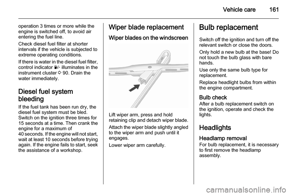
Wiper blades on the windscreen
Lift wiper arm, press and hold
retaining clip and detach wiper blade.
Attach the wiper blade slightly angled
to the wiper arm and push until it
engages.
Lower wiper arm carefully.
Bulb replacement
Switch off the ignition and turn off the
relevant switch or close the doors.
Only hold a new bulb at the base! Do not touch the bulb glass with bare
hands.
Use only the same bulb type for
replacement.
Replace headlight bulbs from within
the engine compartment.
Bulb check After a bulb replacement switch on
the ignition, operate and check the
lights.
Headlights
Headlamp removal For bulb replacement, it is necessary
to first remove the headlamp
assembly.
Page 164 of 223

162Vehicle care
1. Switch off the ignition andheadlight switch.
2. Open the bonnet, release the 11 retainers and remove the
radiator cover.
3. Remove 3 bolts and withdraw headlamp.
4. Depress harness connector tags and disconnect headlamp wiring.
5. Remove the headlamp assembly.
Headlamp assembly installation is the
reverse of removal - ensure locating
dowel aligns with its socket. Do not
overtighten bolts or retainers.
Halogen headlights
Halogen headlights A can be
identified from Xenon headlights B by
the different lens layout.
Low and high beam
Halogen headlights have separate
systems for high beam 1 (inner bulbs)
and low beam 2 (outer bulbs).
1. Remove headlamp assembly 3 161.
2. Remove headlamp cap.
3. Release bulb retaining spring and
remove bulb from reflector
housing.
4. When inserting a new bulb, ensure the lugs engage correctly
with the recesses on the reflector.
Page 169 of 223

Vehicle care167
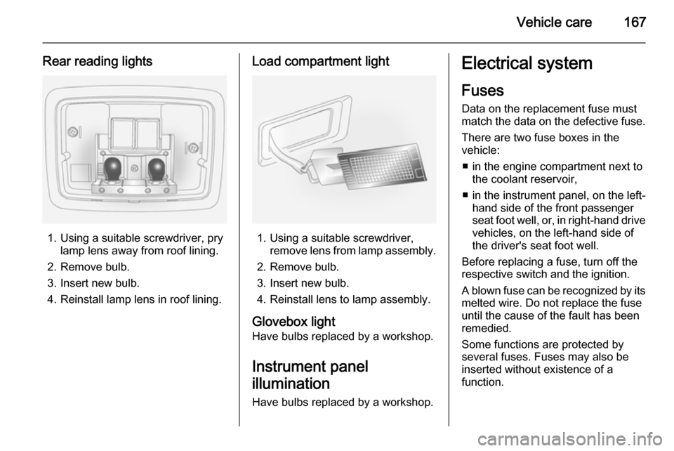
Rear reading lights
1. Using a suitable screwdriver, prylamp lens away from roof lining.
2. Remove bulb.
3. Insert new bulb.
4. Reinstall lamp lens in roof lining.
Load compartment light
1. Using a suitable screwdriver, remove lens from lamp assembly.
2. Remove bulb.
3. Insert new bulb.
4. Reinstall lens to lamp assembly.
Glovebox light
Have bulbs replaced by a workshop.
Instrument panel
illumination Have bulbs replaced by a workshop.
Electrical system
Fuses
Data on the replacement fuse must
match the data on the defective fuse.
There are two fuse boxes in the
vehicle:
■ in the engine compartment next to the coolant reservoir,
■ in the instrument panel, on the left- hand side of the front passenger
seat foot well, or, in right-hand drive
vehicles, on the left-hand side of
the driver's seat foot well.
Before replacing a fuse, turn off the
respective switch and the ignition.
A blown fuse can be recognized by its melted wire. Do not replace the fuse
until the cause of the fault has been
remedied.
Some functions are protected by
several fuses. Fuses may also be
inserted without existence of a
function.
Page 173 of 223

Vehicle care171
FuseCircuitABSAnti-lock Brake
SystemA/CClimate control,
air conditioning
systemBATT1Instrument panel
fuse boxBATT2Instrument panel
fuse boxBATT3Instrument panel
fuse boxBCMBody Control
ModuleECMEngine Control
ModuleECM PWR TRNEngine Control
Module, Power‐
trainENG SNSREngine sensorsEPBElectrical parking
brakeFuseCircuitFAN1Cooling fanFAN3Cooling fanFRT FOGFront fog lightsFRT WPRFront wiperFUEL/VACFuel pump,
vacuum pumpHDLP WASHERHeadlight washerHI BEAM LHHigh beam (left-
hand)HI BEAM RHHigh beam (right-
hand)HORNHornHTD WASH/MIRHeated washer
fluid, heated exte‐
rior mirrorsIGN COIL AIgnition coilIGN COIL BIgnition coilLO BEAM LHLow beam (left-
hand)FuseCircuitLO BEAM RHLow beam (right-
hand)PRK LP LHParking light (left-
hand)PRK LP RHParking light
(right-hand)PWM FANPulse width modu‐ lation fanREAR DEFOGHeated rear
windowREAR WPRRear wiperSPARE–STOP LAMPBrake lightsSTRTRStarterTCMTransmission
Control ModuleTRLR PRL LPTrailer parking
lights
Page 177 of 223

Vehicle care175
FuseCircuitRUN 2Power battery
key on runRUN/CRNKRun crankSDM (BATT)Safety Diag‐
nosis Module
(Battery)SDM (IGN 1)Safety Diag‐
nosis Module
(Ignition)SPARE-S/ROOFSunroofS/ROOF BATTSunroof batterySSPSPower steeringSTR/WHL SWSteering wheelTRLRTrailerTRLR BATTTrailer batteryFuseCircuitXBCMExport Body
Control ModuleXM/HVAC/DLCXM satellite
radio, climate
control, data link
connection
After changing of defective fuses
close the fuse box cover and press
until it engages.
If the fuse box cover is not closed
correctly, malfunctions may occur.
Vehicle tools
Tools
Vehicles with spare wheel
In vehicles with a spare wheel, a jack and vehicle tools kit are available.
The jack and vehicle tools have been
specially developed for your vehicle
and must only be used on that
vehicle. Only use jack for changing
wheels.
The jack and vehicle tools are in a
storage compartment below the floor
cover in the load compartment.
Page 180 of 223

178Vehicle care
V=up to 150 mphW=up to 168 mph
Tyre pressureCheck the pressure of cold tyres at
least every 14 days and before any
long journey. Do not forget the spare
wheel. This also applies to vehicles
with tyre pressure monitoring system.
Use the valve cap key to make
unscrewing the valve caps easier.
The valve cap key is located on the
inside of the tank flap.
Tyre pressure 3 210.
The tyre pressure data refers to cold
tyres. It applies to summer and winter tyres.
Always inflate the spare tyre to the
pressure specified for full load.
The ECO tyre pressure serves to
achieve the smallest amount of fuel
consumption possible.
Incorrect tyre pressures will impair
safety, vehicle handling, comfort and
fuel economy and will increase tyre
wear.
Tyre pressures differ depending on
various options. For the correct tyre
pressure value, follow the procedure
below:
1. Identify the engine identifier code.
Engine data 3 205.
2. Identify the respective tyre.
The tyre pressure tables show all
possible tyre combinations 3 210.
For the tyres approved for your
vehicle, refer to the EEC Certificate of Conformity provided with your vehicle
or other national registration
documents.
The driver is responsible for correct
adjustment of tyre pressure.9 Warning
If the pressure is too low, this can
result in considerable tyre warm-
up and internal damage, leading to tread separation and even to tyre
blow-out at high speeds.
If the tyre pressure must be reduced
or increased on a vehicle with tyre
pressure monitoring system, switch
off ignition.
Tyre pressure monitoring system The tyre pressure monitoring system
checks the pressure of all four wheels
once per minute when vehicle speed
exceeds a certain limit.Caution
Tyre pressure monitoring system
warns only about low tyre pressure
condition and does not replace
regular tyre maintenance by the
driver.
All wheels must be equipped with pressure sensors and the tyres must
have the prescribed pressure. If
wheels without sensors are mounted,
the tyre pressure monitoring system
is not operational.
Page 182 of 223

180Vehicle care
For example, the following messagescan be displayed:
A graphic indicating the left rear tyre
is shown together with the current tyre
pressure; slight pressure deviation.
Reduce speed. Check tyre pressure
at next opportunity with an
appropriate gauge and correct if
necessary.
On the Colour-Info-Display, this
message will appear in yellow.
A graphic indicating the front left tyre is shown together with the current tyre
pressure; significant pressure
deviation or direct pressure loss.
Steer out of the flow of traffic as
quickly as possible without
endangering other vehicles. Stop and check the tyres. Mount the spare
wheel if necessary 3 186.
On the Colour-Info-Display, this
message will appear in red.
Acknowledgement of warnings 3 92,
3 95.
Vehicle messages 3 100.
If the tyre pressure is to be reduced or
increased, switch off the ignition. Tyre
pressures 3 178, 3 210.
Temperature dependency Tyre pressure depends on the
temperature of the tyre. During
driving, tyre temperature and
pressure increase.
The tyre pressure value shown in the Info-Display is the actual tyre
pressure. Therefore it is important to
check tyre pressure with cold tyres.
General information
The use of commercially available
liquid tyre repair kits can impair the
function of the system. Factory-
approved tyre repair kits can be used.
Tyre repair kit 3 183.
External high-power radio equipment
could disrupt the TPMS.
The tyre pressure monitoring system
valve cores and sealing rings must be
replaced each time the tyres are
changed.
Page 183 of 223

Vehicle care181
TPMS sensor matching process
Each TPMS sensor has a unique
identification code. The identification
code must be matched to a new tyre/ wheel position after rotating the tyres
or replacing one or more of the TPMS
sensors.
The TPMS sensor matching process
should also be performed after
replacing a spare tyre with a road tyre containing a TPMS sensor. The
control indicator w and the warning
message should extinguish at the
next ignition cycle.
The sensors are matched to the tyre/
wheel positions, using a TPMS
relearn tool, in the following order:
■ left front tyre
■ right front tyre
■ right rear tyre
■ left rear tyre
Consult your workshop for service or
to purchase a relearn tool.
There are two minutes to match the
first tyre/wheel position, and
five minutes overall to match all fourtyre/wheel positions. If it takes longer,
the matching process stops and must be restarted.
The TPMS sensor matching process
is as follows:
1. Apply the electrical parking brake 3 137 ; on vehicles with automatic
transmission move the selector
lever to position P.
2. Turn the ignition on 3 124.
3. Initiate the TPMS Learn Mode by simultaneously pressing buttons
p and q on the radio remote
control,
- or -
Press the INFO button on the
Infotainment system until a tyre
learn message appears on the
Info-display. Press and hold the
OK button.
The horn sounds twice and the left front turn signal also illuminates
as confirmation that Learn Mode
has been enabled.
4. Start with the left front tyre.5. Place the relearn tool against the tyre sidewall, near the valve stem.Then press the button to activatethe TPMS sensor. A horn chirp
confirms that the sensor
identification code has been
matched to this tyre and wheel
position. The next relevant turn
signal illuminates.
6. Proceed to the right front tyre, and
repeat the procedure in Step 5.
7. Proceed to the right rear tyre, and
repeat the procedure in Step 5.
8. Proceed to the left rear tyre, and repeat the procedure in Step 5.
The horn sounds twice to indicate
the sensor identification code has been matched, and the TPMS
sensor matching process is no
longer active.
9. Turn off the ignition.
10. Set all four tyres to the recommended inflation pressure
3 210.