2015 VAUXHALL ANTARA brake
[x] Cancel search: brakePage 167 of 223

Vehicle care165
1. Remove 2 screws from panel onunderside of vehicle below front
fog lights and remove panel.
2. Disconnect harness connector from bulb holder and rotate bulb
holder anticlockwise.
3. Remove bulb holder from lamp assembly, rotate bulb
anticlockwise and remove from
bulb holder.
4. Insert new bulb into bulb holder and rotate it clockwise.
5. Reinstall bulb holder in lamp assembly and reconnect harnessconnector.
6. Reinstall panel to underside of vehicle using 2 screws removed
earlier.Tail lights
Rear brake, tail, turn signal,
reverse and fog tail light
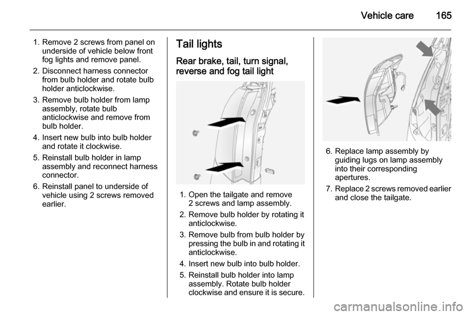
1. Open the tailgate and remove 2 screws and lamp assembly.
2. Remove bulb holder by rotating it anticlockwise.
3. Remove bulb from bulb holder by pressing the bulb in and rotating it
anticlockwise.
4. Insert new bulb into bulb holder.
5. Reinstall bulb holder into lamp assembly. Rotate bulb holder
clockwise and ensure it is secure.
6. Replace lamp assembly by guiding lugs on lamp assembly
into their corresponding
apertures.
7. Replace 2 screws removed earlier
and close the tailgate.
Page 168 of 223

166Vehicle careSide turn signal lights
1. Using a suitable screwdriver, prylamp assembly away from wing.
2. Rotate bulb holder anticlockwise.
3. Remove bulb from lamp assembly
by pulling bulb straight out of bulb holder.
4. Insert new bulb into bulb holder by
pressing it in and rotating the bulb holder clockwise.
5. Push lamp assembly back into aperture.
Centre high-mounted
brake light Have bulbs replaced by a workshop.
Number plate light
1. Remove 4 screws (arrowed) and remove lamp covers.
2. Remove bulb holder from lamp assembly by rotating it
anticlockwise.
3. Pull bulb straight out of bulb holder.
4. Insert new bulb.
5. Reinstall bulb holder into lamp assembly, rotate bulb holder
clockwise and ensure it is secure.
6. Replace lamp covers using the 4 screws removed earlier.
Interior lights
Front reading lights
1. Using a suitable screwdriver, pry lamp lens away from roof lining.
2. Remove bulb.
3. Insert new bulb.
4. Reinstall lamp lens in roof lining.
Page 173 of 223

Vehicle care171
FuseCircuitABSAnti-lock Brake
SystemA/CClimate control,
air conditioning
systemBATT1Instrument panel
fuse boxBATT2Instrument panel
fuse boxBATT3Instrument panel
fuse boxBCMBody Control
ModuleECMEngine Control
ModuleECM PWR TRNEngine Control
Module, Power‐
trainENG SNSREngine sensorsEPBElectrical parking
brakeFuseCircuitFAN1Cooling fanFAN3Cooling fanFRT FOGFront fog lightsFRT WPRFront wiperFUEL/VACFuel pump,
vacuum pumpHDLP WASHERHeadlight washerHI BEAM LHHigh beam (left-
hand)HI BEAM RHHigh beam (right-
hand)HORNHornHTD WASH/MIRHeated washer
fluid, heated exte‐
rior mirrorsIGN COIL AIgnition coilIGN COIL BIgnition coilLO BEAM LHLow beam (left-
hand)FuseCircuitLO BEAM RHLow beam (right-
hand)PRK LP LHParking light (left-
hand)PRK LP RHParking light
(right-hand)PWM FANPulse width modu‐ lation fanREAR DEFOGHeated rear
windowREAR WPRRear wiperSPARE–STOP LAMPBrake lightsSTRTRStarterTCMTransmission
Control ModuleTRLR PRL LPTrailer parking
lights
Page 176 of 223

174Vehicle care
FuseCircuitAMPAmplifierAPO JACK
(CONSOLE)Power outlet
(centre console)APO JACK
(REAR CARGO)Power outlet
(load compart‐
ment)AWD/VENTAll-wheel drive,
ventilationBCM (CTSY)Courtesy lightsBCM (DIMMER)Instrument illu‐
minationBCM (INT LIGHT
TRLR FOG)Interior lights,
trailer fog lightBCM (PRK/TRN)Parking lights,
turn signalsBCM (STOP)Brake lightsBCM (TRN SIG)Turn signalsBCM (VBATT)Battery voltageFuseCircuitCIMCommunica‐
tions Integration
ModuleCLSTRInstrument
clusterDRLDaytime running
lightsDR/LCKDriver door lockDRVR PWR
SEATDriver power
seatDRV/PWR
WNDWDriver power
windowF/DOOR LOCKFuel filler flapFRT WSRFront washerFSCMFuel systemFSCM/VENT SOLFuel system,
vent solenoidHEATING MAT
SWHeating mat
switchHTD SEAT PWRSeat heatingFuseCircuitHVAC BLWRClimate control,
air conditioning
fanIPCInstrument panel clusterISRVM/RCMInterior mirror,
remote compass moduleKEY CAPTUREKey captureL/GATETailgateLOGISTIC MODELogistic modeOSRVMExterior mirrorsPASS PWR
WNDWPassenger
power windowPWR DIODEPower diodePWR MODINGPower modingRADIORadioRR FOGHeated rear
window
Page 183 of 223

Vehicle care181
TPMS sensor matching process
Each TPMS sensor has a unique
identification code. The identification
code must be matched to a new tyre/ wheel position after rotating the tyres
or replacing one or more of the TPMS
sensors.
The TPMS sensor matching process
should also be performed after
replacing a spare tyre with a road tyre containing a TPMS sensor. The
control indicator w and the warning
message should extinguish at the
next ignition cycle.
The sensors are matched to the tyre/
wheel positions, using a TPMS
relearn tool, in the following order:
■ left front tyre
■ right front tyre
■ right rear tyre
■ left rear tyre
Consult your workshop for service or
to purchase a relearn tool.
There are two minutes to match the
first tyre/wheel position, and
five minutes overall to match all fourtyre/wheel positions. If it takes longer,
the matching process stops and must be restarted.
The TPMS sensor matching process
is as follows:
1. Apply the electrical parking brake 3 137 ; on vehicles with automatic
transmission move the selector
lever to position P.
2. Turn the ignition on 3 124.
3. Initiate the TPMS Learn Mode by simultaneously pressing buttons
p and q on the radio remote
control,
- or -
Press the INFO button on the
Infotainment system until a tyre
learn message appears on the
Info-display. Press and hold the
OK button.
The horn sounds twice and the left front turn signal also illuminates
as confirmation that Learn Mode
has been enabled.
4. Start with the left front tyre.5. Place the relearn tool against the tyre sidewall, near the valve stem.Then press the button to activatethe TPMS sensor. A horn chirp
confirms that the sensor
identification code has been
matched to this tyre and wheel
position. The next relevant turn
signal illuminates.
6. Proceed to the right front tyre, and
repeat the procedure in Step 5.
7. Proceed to the right rear tyre, and
repeat the procedure in Step 5.
8. Proceed to the left rear tyre, and repeat the procedure in Step 5.
The horn sounds twice to indicate
the sensor identification code has been matched, and the TPMS
sensor matching process is no
longer active.
9. Turn off the ignition.
10. Set all four tyres to the recommended inflation pressure
3 210.
Page 184 of 223

182Vehicle careTread depth
Check tread depth at regular
intervals.
Tyres should be replaced for safety
reasons at a tread depth of 2-3 mm
(4 mm for winter tyres).
For safety reasons it is recommended that the tread depth of the tyres on
one axle should not vary by more than
2 mm.
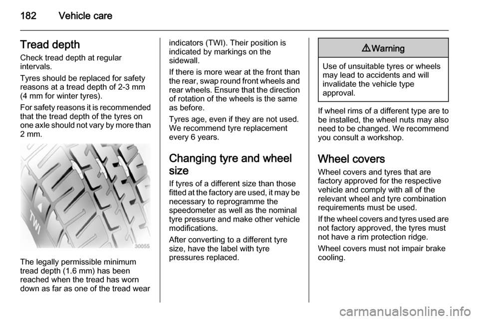
The legally permissible minimum
tread depth (1.6 mm) has been
reached when the tread has worn
down as far as one of the tread wear
indicators (TWI). Their position is
indicated by markings on the
sidewall.
If there is more wear at the front than
the rear, swap round front wheels and rear wheels. Ensure that the direction
of rotation of the wheels is the same
as before.
Tyres age, even if they are not used.
We recommend tyre replacement
every 6 years.
Changing tyre and wheel
size
If tyres of a different size than those
fitted at the factory are used, it may be necessary to reprogramme the
speedometer as well as the nominal tyre pressure and make other vehicle modifications.
After converting to a different tyre
size, have the label with tyre
pressures replaced.9 Warning
Use of unsuitable tyres or wheels
may lead to accidents and will
invalidate the vehicle type
approval.
If wheel rims of a different type are to
be installed, the wheel nuts may also
need to be changed. We recommend you consult a workshop.
Wheel covers Wheel covers and tyres that are
factory approved for the respective
vehicle and comply with all of the
relevant wheel and tyre combination
requirements must be used.
If the wheel covers and tyres used are
not factory approved, the tyres must
not have a rim protection ridge.
Wheel covers must not impair brake
cooling.
Page 185 of 223

Vehicle care1839Warning
Use of unsuitable tyres or wheel
covers could lead to sudden
pressure loss and thereby
accidents.
Tyre chains
Tyre chains are only permitted on the
front wheels.
They must be fitted to the tyres
symmetrically in order to achieve a
concentric fit.
Always use fine mesh chains that add no more than 15 mm to the tyre tread
and the inboard sides (including chain lock).9 Warning
Damage may lead to tyre blowout.
Tyre chains are permitted only on
16 inch wheels. We recommend you consult a workshop.
If the use of tyre chains is required
after suffering a flat front tyre, fit the
temporary spare wheel on the rear
axle and transfer one of the rear
wheels to the front axle.
General
The use of tyre chains is not permitted on the temporary spare wheel.
Tyre repair kit
Minor damage to the tyre tread or
sidewall can be repaired with the tyre
repair kit.
Do not remove foreign bodies from
the tyres.
Tyre damage exceeding 4 mm or that
is at the tyre's sidewall near the rim
cannot be repaired with the tyre repair kit.
In vehicles with a tyre repair kit, there may not be a jack and vehicle tool kit.
Vehicle tools 3 175.
Temporary spare wheel 3 189.9 Warning
Do not drive faster than 50 mph.
Do not use for a lengthy period.
Steering and handling may be
affected.
If you have a flat tyre:
Apply the electrical parking brake
3 137 and engage first gear, reverse
gear or P.
The tyre repair kit is in a storage
compartment below the floor cover in the load compartment.
To remove the tyre repair kit, open the
tailgate.
Page 188 of 223

186Vehicle care
13.Turn the selector switch clockwise
to the air only position. Switch on
the compressor to inflate the tyre
with air only.
Notice
The driving characteristic of the
repaired tyre is severely affected,
therefore have this tyre replaced.
If unusual noise is heard or the
compressor becomes hot, turn
compressor off for at least
30 minutes.
Note the expiry date of the kit. After
this date its sealing capability is no
longer guaranteed. Pay attention to
storage information on sealant
canister.
Replace the used sealant canister.
To remove sealant canister, release sealant filler hose and air hose, slide
canister out of housing and unscrew hose from canister. Dispose of thecanister as prescribed by applicable
laws.
The accessory adapter supplied can
be used to pump up other items
e.g. footballs, air mattresses,
inflatable dinghies etc. The adapter
is located on the underside of the
tyre repair kit.
Wheel changing Some vehicles are equipped with a
tyre repair kit instead of a spare wheel 3 183.Make the following preparations and
observe the following information:
■ Park the vehicle on a level, firm and
non-slippery surface. The frontwheels must be in the straight-
ahead position.
■ Apply the electrical parking brake 3 137 and engage first gear,
reverse gear or P.
■ Remove the spare wheel 3 189.
■ Never change more than one wheel
at a time.
■ Block wheel diagonally opposite the wheel to be changed, by placing
wedge blocks or equivalent in front
and behind the wheel.
■ Use the jack only to change wheels
in case of puncture, not for
seasonal winter or summer tyre
changes.
■ Never exceed jack maximum working load (900 kg).
■ If the ground on which the vehicle is standing is soft, a solid board
(max. 1 cm thick) should be placed
under the jack.