Page 346 of 564

346 3-5. Other interior features
CAUTION
Observe the following precautions.
Failure to do so may cause the driver's floor mat to slip, possibly interfering
with the pedals while driving. An unexpectedly high speed may result or it may
become difficult to stop the vehicle, leading to a serious accident.
When installing the driver's floor mat
Do not use floor mats designed for other models or different model year
vehicles, even if they are Toyota Genuine floor mats.
Only use floor mats designed for the driver's seat.
Always install the floor mat securely using the retaining hooks (clips) pro-
vided.
Do not use two or more floor mats on top of each other.
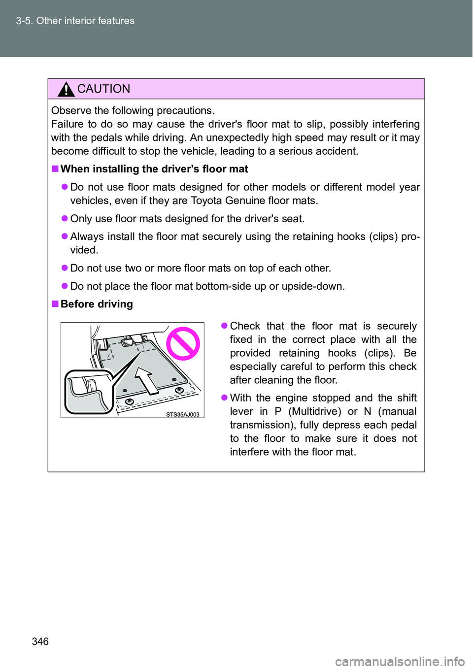
Do not place the floor mat bottom-side up or upside-down.
Before driving
Check that the floor mat is securely
fixed in the correct place with all the
provided retaining hooks (clips). Be
especially careful to perform this check
after cleaning the floor.
With the engine stopped and the shift
lever in P (Multidrive) or N (manual
transmission), fully depress each pedal
to the floor to make sure it does not
interfere with the floor mat.
Page 347 of 564
347
3-5. Other interior features
3
Interior features
Luggage compar tment features
Cargo hooks
Pull the hook down to use.
The cargo hooks are provided
for securing loose items.
Dual-level deck board (if equipped)
The position of the dual-level
deck board can be changed
(lowered/raised). (P. 349)
Deck board
Page 350 of 564
350 3-5. Other interior features
Removing the dual-level deck board
Before removing, raise the dual-level deck board to the upper posi-
tion. If it is in the lower position, the board cannot be removed.
Lift the dual-level deck board up.
Lift the dual-level deck board fur-
ther upward through the portion
“A” in the illustration.
Securing the dual-level deck board
Lift the dual-level deck board up.
STEP1
STEP2
A
STEP1
Page 380 of 564

380 4-3. Do-it-yourself maintenance
Add distilled water.
If the “UPPER LEVEL” line cannot be seen, check the fluid level by
looking directly at the cell.
Put the vent plug back on and close it securely.
Before recharging
When recharging, the battery produces hydrogen gas which is flammable
and explosive. Therefore, observe the following before recharging:
If recharging with the battery installed on the vehicle, be sure to discon-
nect the ground cable.
Make sure the power switch on the charger is off when connecting and
disconnecting the charger cables to the battery.
After recharging/reconnecting the battery (vehicles with a smart entry
& start system)
Unlocking the doors using the smart entry & start system may not be
possible immediately after reconnecting the battery. If this happens, use
the wireless remote control or the mechanical key to lock/unlock the
doors.
Start the engine with the “ENGINE START STOP” switch in ACCES-
SORY mode. The engine may not start with the “ENGINE START STOP”
switch turned off. However, the engine will operate normally from the sec-
ond attempt.
The “ENGINE START STOP” switch mode is recorded by the vehicle. If
the battery is reconnected, the vehicle will return the “ENGINE START
STOP” switch mode to the status it was in before the battery was discon-
nected. Make sure to turn off the engine before disconnect the battery.
Take extra care when connecting the battery if the “ENGINE START
STOP” switch mode prior to discharge is unknown.
If the engine will not start even after multiple attempts, contact any autho-
rized Toyota dealer or repairer, or another duly qualified and equipped pro-
fessional.
STEP2
STEP3
Page 415 of 564
415 4-3. Do-it-yourself maintenance
4
Maintenance and care
5 IG2 10 ASmart entry & start system, multi-
port fuel injection system/sequen-
tial multiport fuel injection system,
SRS airbag system, steering lock
system, stop lights, Stop & Start
system
6 IGN 15 AMultiport fuel injection system/
sequential multiport fuel injection
system
7MET 7.5 AGauge and meters, Stop & Start
system
8PWR HTR
*225 APower heater, multiport fuel injec-
tion system/sequential multiport
fuel injection system
9 EPS 50 A Electric power steering
10 ABS NO.2 30 A ABS, VSC
11 DEF 30 A Rear window defogger
12 SPARE 10 A Spare fuse
13 PTC 80 APTC heater, outside rear view mir-
ror defoggers
14 HTR 40 A Air conditioning system
15 H-LP CLN 30 A
16 RDI FAN 30 A Electric cooling fan
17 ABS NO.1 50 A ABS, VSC
18 BBC
*340 A Stop & Start system
19 ST 30 A Starting system
20 AMP 15 A
21 D/L NO.2 25 A
Power door lock
22 D.C.C. 30 A DOME, ECU-B NO.1
23 STR LOCK 20 A Steering lock system
FuseAmpereCircuit
Page 416 of 564
416 4-3. Do-it-yourself maintenance
*1: Vehicles with a gasoline engine
*2: Vehicles with a diesel engine
*3: Vehicles with a 1NR-FE engine (with a Stop & Start system) 24 ECU-B NO.1 5 AMain body ECU, smart entry & start
system
25 DOME 15 A Interior lights, audio system, VSC
26 ETCS 10 AMultiport fuel injection system/
sequential multiport fuel injection
system
27 HAZ 10 A Turn signal lights
28 AM2 7.5 AMultiport fuel injection system/
sequential multiport fuel injection
system, smart entry & start system,
starting system
29 ECU-B NO.2 5 AGauge and meters, power door
lock, wireless remote control, Stop
& Start system, smart entry & start
system, air conditioning system,
tire pressure warning system
30 ALT-S 7.5 A
31 R/I 50 AEFI MAIN, ECD MAIN, EFI NO.2,
EFI NO.3, IG2, IGN, MET, HORN
32 SPARE 20 A Spare fuse
33 SPARE 30 A Spare fuse
34 MIR-HTR 10 A
35 ID/UP 7.5 AMultiport fuel injection system/
sequential multiport fuel injection
system
FuseAmpereCircuit
Page 418 of 564
418 4-3. Do-it-yourself maintenance
Type C (vehicles with a gasoline engine)
FuseAmpereCircuit
1 ALT 120 AEPS, ABS NO.2, DEF, PTC, HTR,
RDI FAN, ABS NO.1, TAIL NO.2,
PANEL, DOOR R/R, DOOR P,
ECU-IG NO.1, ECU-IG NO.2, A/C,
GAUGE, WASHER, WIPER,
WIPER RR, P/W, DOOR R/L,
DOOR, CIG, ACC, D/L, OBD, FOG
RR, STOP, AM1, FOG FR, D-D/L,
SHADE, S-HTR
2MAIN 80 ABBC, ST, D/L NO.2, D.C.C., STR
LOCK, ETCS, HAZ, AM2, ECU-B
NO.2, R/I, S-HORN, H-LP MAIN,
H-LP RH HI, H-LP LH HI, H-LP RH
LO, H-LP LH LO
Page 419 of 564
419 4-3. Do-it-yourself maintenance
4
Maintenance and care
Type C (vehicles with a diesel engine)
FuseAmpereCircuit
1 ALT 120 APWR HTR, EPS, ABS NO.2, DEF,
PTC, HTR, RDI FAN, ABS NO.1,
TAIL NO.2, PANEL, DOOR R/R,
DOOR P, ECU-IG NO.1, ECU-IG
NO.2, A/C, GAUGE, WASHER,
WIPER, WIPER RR, P/W, DOOR
R/L, DOOR, CIG, ACC, D/L, OBD,
FOG RR, STOP, AM1, FOG FR,
D-D/L, SHADE, S-HTR
2MAIN 80 AST, D/L NO.2, D.C.C., STR LOCK,
ETCS, HAZ, AM2, ECU-B NO.2,
R/I, H-LP MAIN, H-LP RH HI, H-LP
LH HI, H-LP RH LO, H-LP LH LO,
MMT
3 GLOW DC/DC 80 A Engine glow system