Page 292 of 650
292 2-4. Using other driving systems
CAUTION
Replacing tires
Make sure that all tires are of the same size, brand, tread pattern and total
load capacity. In addition, make sure that the tires are inflated to the speci-
fied tire pressure level.
The ABS and VSC+ systems will not function correctly if different tires are fit-
ted on the vehicle.
Contact any authorized Toyota dealer or repairer, or another duly qualified
and equipped professional for further information when replacing tires or
wheels.
Handling of tires and suspension
Using tires with any kind of problem or modifying the suspension will affect
the driving assist systems, and may cause the system to malfunction.
VERSO_WE.book Page 292 Thursday, June 19, 2014 11:31 AM
Page 474 of 650
474 4-3. Do-it-yourself maintenance
Fuse layout and amperage ratings
Engine compartment
FuseAmpereCircuit
1TO IP J/B*1120 AECU-IG NO.2, HTR-IG, WIPER,
RR WIPER, WASHER, ECU-IG
NO.1, ECU-IG NO.3, SEAT HTR,
AM1*4, DOOR, STOP, FR DOOR,
POWER, RR DOOR, RL DOOR,
OBD, ACC-B, RR FOG, FR FOG,
DEF, TAIL, SUNROOF, DRL
2H-LP CLN30 A Headlight cleaners
3RDI FAN40 A Electric cooling fan(s)
4CDS FAN*1,*230 A Electric cooling fan(s)
5 ABS NO.1 50 A Anti-lock brake system, VSC+
6 HTR
*2,*350 A Air conditioning system
VERSO_WE.book Page 474 Thursday, June 19, 2014 11:31 AM
Page 475 of 650

475 4-3. Do-it-yourself maintenance
4
Maintenance and care
7ALT120 A
*3
Charging system, RDI FAN, CDS
FAN, H-LP CLN, ABS NO.1, ABS
NO.2, HTR, STV HTR
*2, PWR
OUTLET, HTR SUB NO.1, HTR
SUB NO.2, HTR SUB NO.3, ECU-
IG NO.2, HTR-IG, WIPER, RR
WIPER, WASHER, ECU-IG NO.1,
ECU-IG NO.3, SEAT HTR, AM1
*4,
DOOR, STOP, FR DOOR,
POWER, RR DOOR, RL DOOR,
OBD, ACC-B, RR FOG, FR FOG,
DEF, TAIL, SUNROOF, DRL 140 A
*2
8EPS*2,*380 A Electric power steering
GLOW
*180 A Engine glow system
9GLOW
*280 A Engine glow system
EPS
*180 A Electric power steering
10 P-SYSTEM
*330 A VALVEMATIC system
11EFI MAIN
*250 AEFI NO.1, EFI NO.2, EFI NO.3*7,
EFI NO.4
FUEL HTR
*150 A Fuel heater
12P/I
*2,*350 AEDU*2, EFI MAIN*3, IGT/INJ*3,
HORN, IG2
H-LP MAIN
*150 AH-LP LH LO, H-LP RH LO, H-LP LH
HI, H-LP RH HI
13H-LP MAIN
*2,*350 AH-LP LH LO, H-LP RH LO, H-LP
LH HI, H-LP RH HI
P/I
*150 A HORN, IG2, ELEC FUEL PMP
14 BBC
*140 A Stop & Start system
15 EFI MAIN
*150 A EFI NO.1, EFI NO.2, EFI NO.4
16 SPARE 10 A Spare fuse
17 SPARE 30 A Spare fuse
FuseAmpereCircuit
VERSO_WE.book Page 475 Thursday, June 19, 2014 11:31 AM
Page 477 of 650

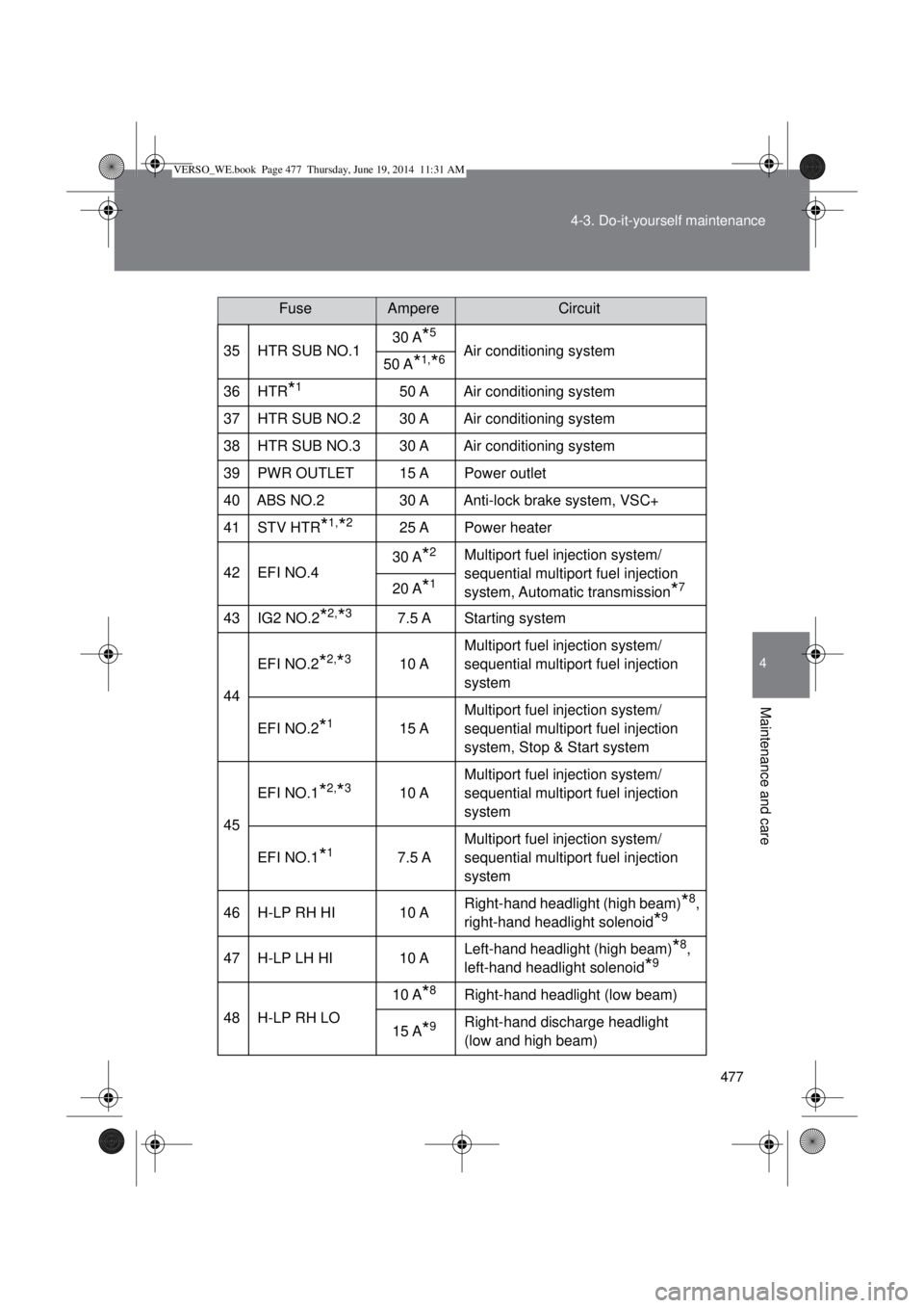
477 4-3. Do-it-yourself maintenance
4
Maintenance and care
35 HTR SUB NO.130 A*5
Air conditioning system
50 A*1,*6
36 HTR*150 A Air conditioning system
37 HTR SUB NO.2 30 A Air conditioning system
38 HTR SUB NO.3 30 A Air conditioning system
39PWR OUTLET15 APower outlet
40 ABS NO.2 30 A Anti-lock brake system, VSC+
41 STV HTR
*1,*225 A Power heater
42 EFI NO.430 A
*2Multiport fuel injection system/
sequential multiport fuel injection
system, Automatic transmission
*720 A*1
43 IG2 NO.2*2,*37.5 A Starting system
44EFI NO.2
*2,*310 AMultiport fuel injection system/
sequential multiport fuel injection
system
EFI NO.2
*115 AMultiport fuel injection system/
sequential multiport fuel injection
system, Stop & Start system
45EFI NO.1
*2,*310 AMultiport fuel injection system/
sequential multiport fuel injection
system
EFI NO.1
*17.5 AMultiport fuel injection system/
sequential multiport fuel injection
system
46 H-LP RH HI 10 ARight-hand headlight (high beam)
*8,
right-hand headlight solenoid
*9
47 H-LP LH HI 10 ALeft-hand headlight (high beam)*8,
left-hand headlight solenoid
*9
48 H-LP RH LO10 A
*8Right-hand headlight (low beam)
15 A
*9Right-hand discharge headlight
(low and high beam)
FuseAmpereCircuit
VERSO_WE.book Page 477 Thursday, June 19, 2014 11:31 AM
Page 488 of 650
488 4-3. Do-it-yourself maintenance
Turn the bulb base counterclock-
wise.
Unplug the connector while pull-
ing the lock release.
Replace the light bulb, and install
the bulb base.
Align the 3 tabs on the light bulb
with the mounting, and insert.
Turn and secure the bulb base.
Shake the bulb base gently to
check that it is not loose, turn the
headlight low beam on once and
visually confirm that no light is
leaking through the mounting.
VERSO_WE.book Page 488 Thursday, June 19, 2014 11:31 AM
Page 490 of 650
490 4-3. Do-it-yourself maintenance
Turn the bulb base counterclock-
wise.
Unplug the connector while pull-
ing the lock release.
Replace the light bulb, and install
the bulb base.
Align the 3 tabs on the light bulb
with the mounting, and insert.
Turn and secure the bulb base.
Shake the bulb base gently to
check that it is not loose, turn the
headlight high beam on once and
visually confirm that no light is
leaking through the mounting.
VERSO_WE.book Page 490 Thursday, June 19, 2014 11:31 AM
Page 492 of 650
492 4-3. Do-it-yourself maintenance
Unplug the connector while
depressing the lock release.
Turn the bulb base counterclock-
wise.
Replace the light bulb, and install
the bulb base.
Align the 3 tabs on the light bulb
with the mounting, and insert.
Turn and secure the bulb base.
Shake the bulb base gently to
check that it is not loose, turn the
front fog light on once and visu-
ally confirm that no light is leaking
through the mounting.
VERSO_WE.book Page 492 Thursday, June 19, 2014 11:31 AM
Page 515 of 650

5
515 5-2. Steps to take in an emergency
When trouble arises
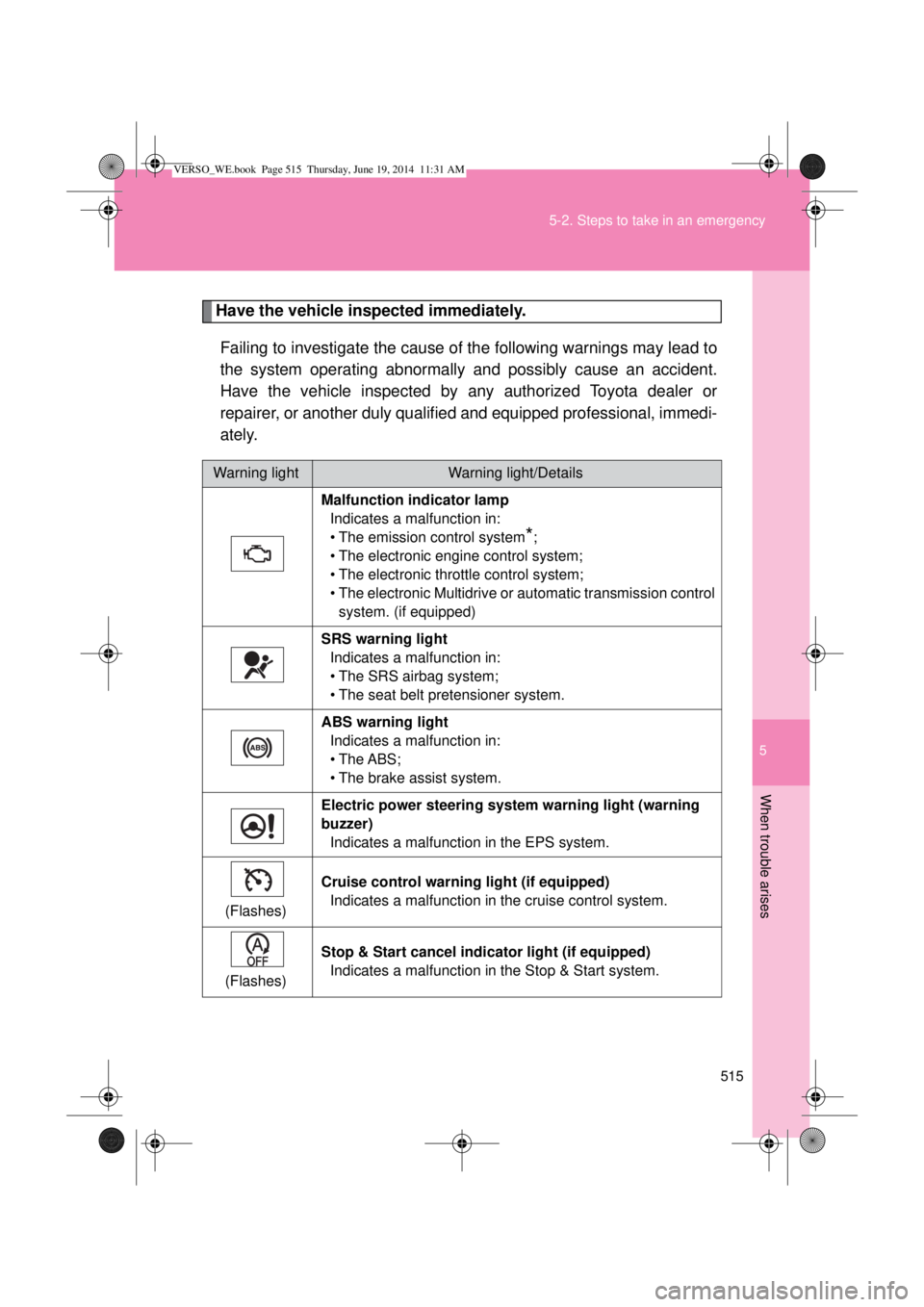
Have the vehicle inspected immediately.
Failing to investigate the cause of the following warnings may lead to
the system operating abnormally and possibly cause an accident.
Have the vehicle inspected by any authorized Toyota dealer or
repairer, or another duly qualified and equipped professional, immedi-
ately.
Warning lightWarning light/Details
Malfunction indicator lamp
Indicates a malfunction in:
• The emission control system
*;
• The electronic engine control system;
• The electronic throttle control system;
• The electronic Multidrive or automatic transmission control
system. (if equipped)
SRS warning light
Indicates a malfunction in:
• The SRS airbag system;
• The seat belt pretensioner system.
ABS warning light
Indicates a malfunction in:
• The ABS;
• The brake assist system.
Electric power steering system warning light (warning
buzzer)
Indicates a malfunction in the EPS system.
(Flashes)Cruise control warning light (if equipped)
Indicates a malfunction in the cruise control system.
(Flashes)Stop & Start cancel indicator light (if equipped)
Indicates a malfunction in the Stop & Start system.
VERSO_WE.book Page 515 Thursday, June 19, 2014 11:31 AM