2015 TOYOTA SIENNA ignition
[x] Cancel search: ignitionPage 418 of 664

4186-1. Using the air conditioning system and defogger
SIENNA_OM_01999-08001_(U)
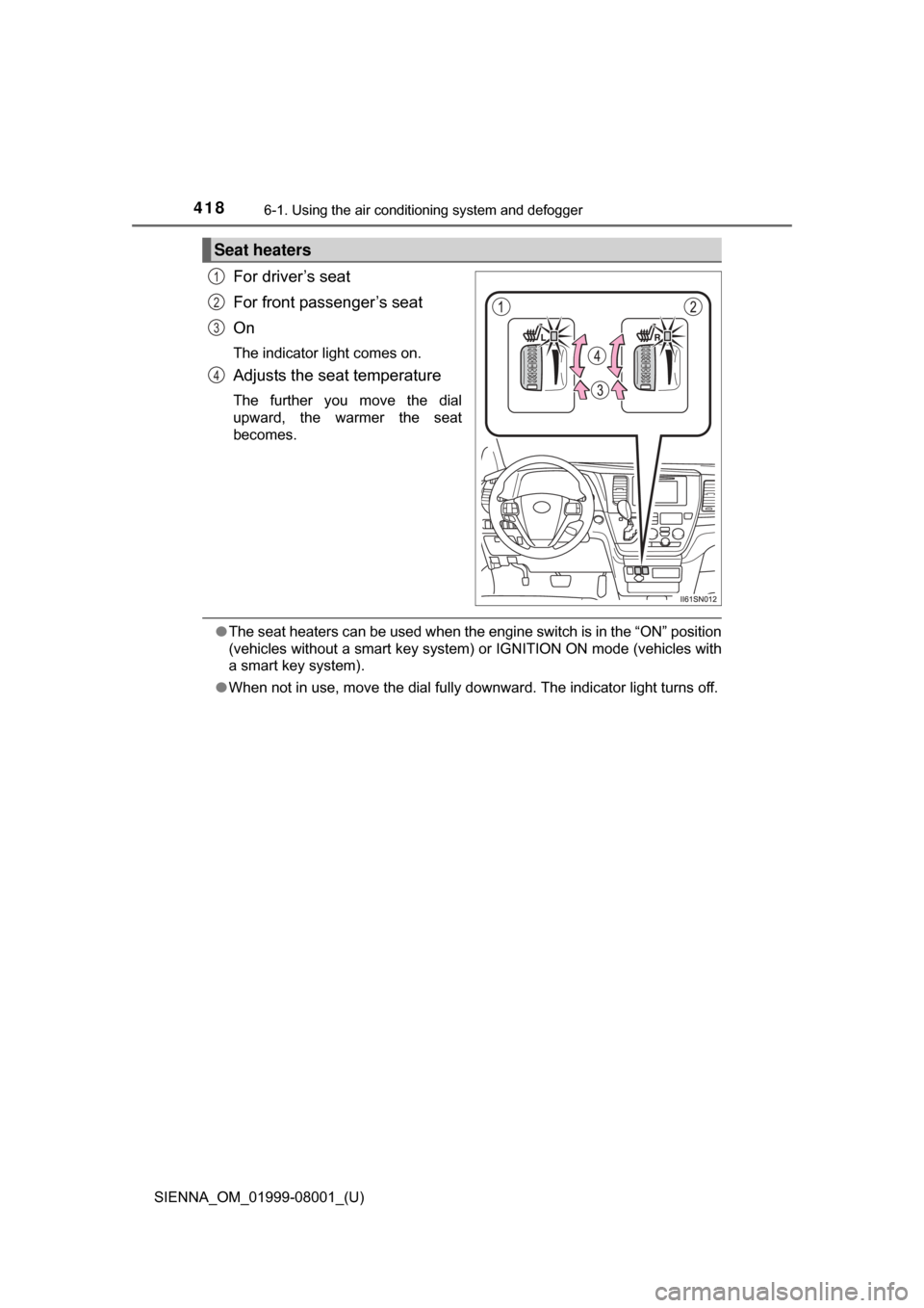
For driver’s seat
For front passenger’s seat
On
The indicator light comes on.
Adjusts the seat temperature
The further you move the dial
upward, the warmer the seat
becomes.
●The seat heaters can be used when the engine switch is in the “ON” position
(vehicles without a smart key system ) or IGNITION ON mode (vehicles with
a smart key system).
● When not in use, move the dial fully downward. The indicator light turns off.
Seat heaters
1
2
3
4
Page 439 of 664

SIENNA_OM_01999-08001_(U)
4396-4. Using the other interior features
6
Interior features
■The power outlet can be used when
Vehicles without a smart key system
12 V: The engine switch is in the “ACC” or “ON” position.
120 V AC: The engine switch is in the “ON” position.
Vehicles with a smart key system
12 V: The engine switch is in ACCESSORY or IGNITION ON mode.
120 V AC: The engine switch is in IGNITION ON mode.
NOTICE
■ To avoid damaging the power outlet
Close the power outlet lid when the power outlet is not in use.
Foreign objects or liquids that enter the power outlet may cause a short cir-
cuit.
■ To prevent blown fuse
12 V
Do not use an accessory that uses more than 12 V 10 A.
120 V AC
Do not use a 120 V AC appliance that requires more than 100 W.
If a 120 V AC appliance that consumes more than 100 W is used, the pro-
tection circuit may cut the power supply.
■ To prevent battery discharge
Do not use the power outlet longer than necessary when the engine is not
running.
■ Appliances that may not operate properly (120 V AC)
The following 120 V AC appliances may not operate properly even if their
power consumption is under 100 W:
● Appliances with high initial peak wattage
● Measuring devices that process precise data
● Other appliances that require an extremely stable power supply
Page 455 of 664

SIENNA_OM_01999-08001_(U)
4556-4. Using the other interior features
6
Interior features
■Safety Connect Services Information
●Phone calls using the vehicles Bluetooth® technology will not be possible
during Safety Connect.
● Safety Connect is available beginning Fall 2009 on select Toyota models.
Contact with the Safety Connect response center is dependent upon the
telematics device being in operative condition, cellular connection availabil-
ity, and GPS satellite signal reception, which can limit the ability to reach the
response center or receive emergency service support. Enrollment and
Telematics Subscription Service Agreement are required. A variety of sub-
scription terms is available; charges vary by subscription term selected.
● Automatic Collision Notification, Emergency Assistance, Stolen Vehicle
Location, and Enhanced Roadside Assistance will function in the United
States, including Hawaii and Alaska, and in Canada. No Safety Connect
services will function outside of the United States in countries other than
Canada.
● Safety Connect services are not subject to section 255 of the Telecommuni-
cations Act and the device is not TTY compatible.
■ Languages
The Safety Connect response center will offer support in multiple languages.
The Safety Connect system will offer voice prompts in English and Spanish.
Please indicate your language of choice when enrolling.
■ When contacting th e response center
You may be unable to contact the response center if the network is busy.
When the engine switch is turned to the “ON” position (vehicles with-
out a smart key system) or IGNITION ON mode (vehicles with a smart
key system), the red indicator light comes on for 2 seconds then turns
off. Afterward, the green indicator light comes on, indicating that the
service is active.
The following indicator light patterns indicate specific system usage
conditions:
● Green indicator light on = Active service
● Green indicator light flashing = Sa fety Connect call in process
● Red indicator light (except at vehi cle start-up) = System malfunction
(contact your Toyota dealer)
● No indicator light (off) = Safety Connect service not active
Safety Connect LE D light Indicators
Page 467 of 664

SIENNA_OM_01999-08001_(U)
4677-2. Maintenance
7
Maintenance and care
■Repair and replacement
It is recommended that genuine Toyota parts be used for repairs to ensure
performance of each system. If non-Toyota parts are used in replacement or if
a repair shop other than a Toyota dealer performs repairs, confirm the war-
ranty coverage.
■ Resetting the message indicating maintenance is required (U.S.A. only)
After the required maintenance is preformed according to the maintenance
schedule, please reset the message.
To reset the data, follow the procedures described below:
Using the odometer and trip meter display
Turn the engine switch to the “LOCK” position (vehicles without a smart key
system) or off (vehicles with a smart key system) with the trip meter A read-
ing shown. ( P. 88)
While pressing the odometer/trip meter display change button (P. 87),
turn the engine switch to the “ON” position (vehicles without a smart key
system) or IGNITION ON mode (vehicles with a smart key system) (do not
start the engine because otherwise the reset mode will be canceled).
Continue to press and hold the button until the trip meter displays “000000”
and the multi-information display indicates that the reset is complete.
Using the multi-information display (vehicles with color display)
While the engine is running, switch the multi-information display to the
“Settings” screen. ( P. 618)
Select “Maintenance Reset” on the “Settings” screen.
Select “Yes” on the “Maintenance Reset” screen.
“Maintenance Reset Complete” will be displayed on the multi-information dis-
play when the reset procedure has been completed.
■ Allow inspection and repairs to be performed by a Toyota dealer
●Toyota technicians are well-trained specialists and are kept up to date with
the latest service information. They are well informed about the operations
of all systems on your vehicle.
● Keep a copy of the repair order. It proves that the maintenance that has
been performed is under warranty cove rage. If any problem should arise
while your vehicle is under warranty, your Toyota dealer will promptly take
care of it.
1
2
3
1
2
3
Page 489 of 664

SIENNA_OM_01999-08001_(U)
4897-3. Do-it-yourself maintenance
7
Maintenance and care
Your vehicle is equipped with a tire pressure warning system that uses
tire pressure warning valves and tr ansmitters to detect low tire infla-
tion pressure before serious problems arise. ( P. 539)
Vehicles with compact spare tire : The compact spare tire is not
equipped with the tire pressure warning valve and transmitters.
◆Installing tire pressure warning valves and transmitters
When replacing tires or wheels, tire pressure warning valves and
transmitters must also be installed.
When new tire pressure warning valves and transmitters are
installed, new ID codes must be registered in the tire pressure
warning computer and the tire pr essure warning system must be
initialized. Have tire pressure warning valve and transmitter ID
codes registered by your Toyota dealer. ( P. 490)
◆Initializing the tire pressure warning system
When the tire size is changed, the tire pressure warning system
must be initialized.
When the tire pressure warning system is initialized, the current tire
inflation pressure is set as the benchmark pressure.
■How to initialize the tire pressure warning system
Park the vehicle in a safe place and turn the engine switch off.
Initialization cannot be performed while the vehicle is moving.
Adjust the tire inflation pressure to the specified cold tire inflation
pressure level. ( P. 600)
Make sure to adjust the tire pressu re to the specified cold tire infla-
tion pressure level. The tire pressure warning system will operate
based on this pressure level.
Turn the engine switch to the “ON” position (vehicles without a
smart key system) or IGNITION ON mode (vehicles with a smart
key system).
Tire pressure warning system
1
2
3
Page 490 of 664

490
SIENNA_OM_01999-08001_(U)
7-3. Do-it-yourself maintenance
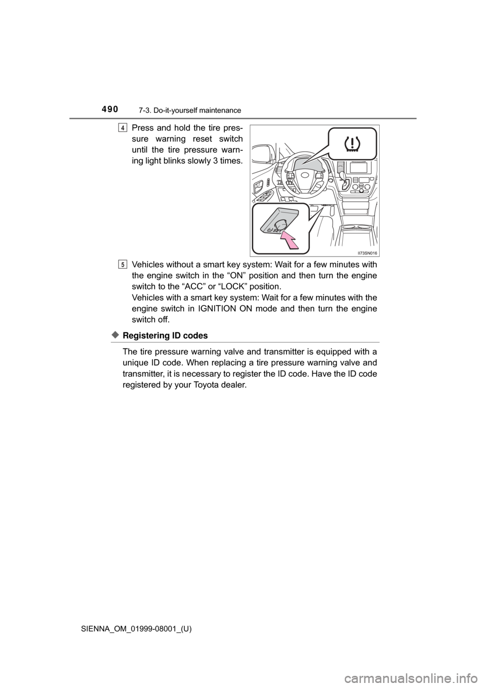
Press and hold the tire pres-
sure warning reset switch
until the tire pressure warn-
ing light blinks slowly 3 times.
Vehicles without a smart key system: Wait for a few minutes with
the engine switch in the “ON” position and then turn the engine
switch to the “ACC” or “LOCK” position.
Vehicles with a smart key system: Wait for a few minutes with the
engine switch in IGNITION ON mode and then turn the engine
switch off.
◆Registering ID codes
The tire pressure warning valve and transmitter is equipped with a
unique ID code. When replacing a tire pressure warning valve and
transmitter, it is necessary to register the ID code. Have the ID code
registered by your Toyota dealer.
4
5
Page 540 of 664

5408-2. Steps to take in an emergency
SIENNA_OM_01999-08001_(U)
*1: Parking brake engaged warning buzzer:P. 550
*2: If equipped
*3: Open door warning buzzer:P. 547
*4: Driver’s seat belt buzzer:
The driver’s seat belt buzzer sounds to alert the driver that his or her seat
belt is not fastened. Once the engine switch is turned to the “ON” position
(vehicles without a smart key system) or IGNITION ON mode (vehicles
with a smart key system), the buzzer sounds for 6 seconds. If the vehicle
reaches a speed of 12 mph (20 km/h), the buzzer sounds once. If the
seat belt is still unfastened after 30 seconds, the buzzer will sound inter-
mittently for 10 seconds. Then, if the seat belt is still unfastened, the
buzzer will sound in a different tone for 20 more seconds.
Front passenger’s seat belt buzzer:
The front passenger’s seat belt buzzer sounds to alert the front passen-
ger that his or her seat belt is not fastened. The buzzer sounds once if the
vehicle reaches a speed of 12 mph (20 km/h). If the seat belt is still unfas-
tened after 30 seconds, the buzzer will sound intermittently for 10 sec-
onds. Then, if the seat belt is still unfastened, the buzzer will sound in a
different tone for 20 more seconds.
Page 584 of 664

5848-2. Steps to take in an emergency
SIENNA_OM_01999-08001_(U)
Connect a positive jumper cable clamp to the positive (+) battery
terminal on your vehicle
Connect the clamp on the other end of the positive cable to the
positive (+) battery terminal on the second vehicle
Connect a negative cable clamp to the negative (-) battery termi-
nal on the second vehicle
Connect the clamp at the other end of the negative cable to a
solid, stationary, unpainted metallic point away from the battery
and any moving parts, as shown in the illustration.
Start the engine of the second vehicle. Increase the engine speed
slightly and maintain at that le vel for approximately 5 minutes to
recharge the batter y of your vehicle.
Vehicles with a smart key system only: Open and close any of the
doors of your vehicle with the engine switch off.
Maintain the engine speed of t he second vehicle and start the
engine of your vehicle by turni ng the engine switch to the “ON”
position (vehicles without a smart key system) or turning the engine
switch to IGNITION ON mode (v ehicles with a smart key system).
Once the vehicle’s engine has started, remove the jumper cables in
the exact reverse order from which they were connected.
To install the engine cover, conduct the removal procedure in
reverse. After installing, check that the fixed pins are inserted
securely.
Once the engine starts, have the vehicle inspected at your Toyota
dealer as soon as possible.1
2
3
4
4
5
6
7
8