2015 SKODA SUPERB manual transmission
[x] Cancel search: manual transmissionPage 226 of 276

WARNINGThe factory-supplied lifting jack is only intended for your model of vehicle.
Under no circumstances attempt to lift heavier vehicles or other loads.
CAUTION
■ Screw the jack back into the starting position before storing in the box with
the tool kit.■
Ensure that the vehicle tool kit is safely secured in the boot.
■
Ensure that the box is always secured with the strap.
Note
The declaration of conformity is included with the jack or the log folder.
Changing a wheel
Introduction
This chapter contains information on the following subjects:
Preparation
224
Removing/stowing the wheel
224
Full wheel trim
225
Wheel bolts
225
Anti-theft wheel bolts
225
Loosening/tightening wheel bolts
226
Raising the vehicle
226
Remove the wheel / fix
227
Follow-up tasks
227
For your own safety and the safety of the passengers, the following instruc-
tions must be observed before changing a wheel on the road.
Switch on the hazard warning lights system.
Place the warning triangle at the prescribed distance.
Park the vehicle as far away as possible from the flowing traffic.
Choose a location with a flat, solid surface.
Have all the occupants get out. The passengers should not stand on the
road (instead they should remain behind a crash barrier, for instance) while
the wheel is being changed.
Tyres with increased puncture resistance
Some vehicles may be fitted with tyres at the factory that have increased
puncture resistance (so-called “SEAL” tyres).
These vehicles are delivered without a puncture repair kit, spare wheel and
appropriate hand tools.
If the tyres with increased puncture resistance are replaced with tyres that
have no increased puncture resistance then the vehicle should be equipped
with a puncture repair kit, spare wheel and appropriate hand tools.
Preparation
Before changing the wheel, the following work must be carried out.
›
Switch off the engine.
›
For vehicles with manual transmission engage 1st gear.
›
On vehicles with
automatic transmission place the selector lever in the P po-
sition.
›
The parking brake switch.
›
Uncouple any trailers.
Removing/stowing the wheel
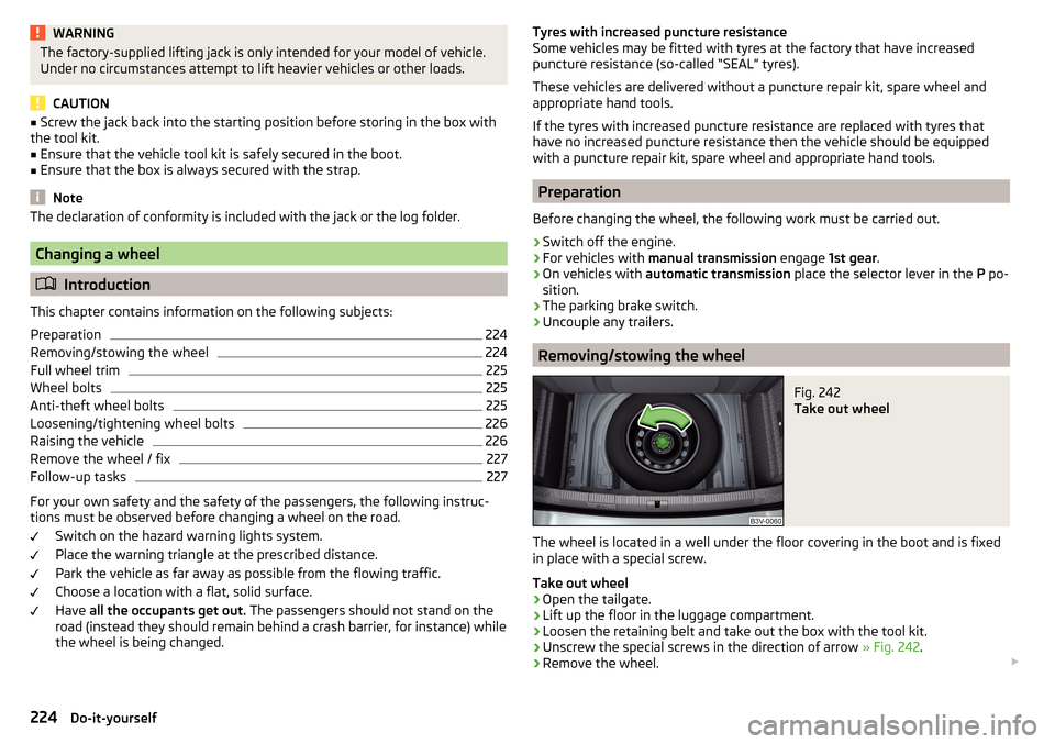
Fig. 242
Take out wheel
The wheel is located in a well under the floor covering in the boot and is fixed
in place with a special screw.
Take out wheel
›
Open the tailgate.
›
Lift up the floor in the luggage compartment.
›
Loosen the retaining belt and take out the box with the tool kit.
›
Unscrew the special screws in the direction of arrow » Fig. 242.
›
Remove the wheel.
224Do-it-yourself
Page 231 of 276

General informationRead and observe
on page 228 first.
For your own safety and the safety of your passengers, the following instruc-
tions must be observed before carrying out a wheel repair on the road.
Switch on the hazard warning lights system.
Place the warning triangle at the prescribed distance.
Park the vehicle as far away as possible from the flowing traffic.
Choose a location with a flat, solid surface.
Have all the occupants get out. The passengers should not stand on the
road (instead they should remain behind a crash barrier, for instance) while
the wheel is being changed.
The breakdown kit must not be used under the following circumstances. ▶ The rim is damaged.
▶ The outside temperature is below -20 ° C.
▶ The cut or puncture is larger than 4 mm.
▶ The tyre wall is damaged.
▶ After the expiration date (see inflation bottle).
Preparations for using the breakdown kit
Read and observe
on page 228 first.
The following preparatory work must be carried out before using the puncturerepair kit.
›
Switch off the engine.
›
For vehicles with manual transmission engage 1st gear.
›
On vehicles with
automatic transmission place the selector lever in the P po-
sition.
›
The parking brake switch.
›
Check that you can carry out the repairs with the breakdown kit » page 228.
›
Uncouple any trailers.
›
Remove the breakdown kit from the boot.
›
Stick the sticker
1
» Fig. 248 on page 228 on the dashboard in the driver's
field of view.
›
Unscrew the valve cap.
›
Use the valve remover
2
to unscrew the valve core and place it on a clean
surface (rag, paper, etc.).
Sealing and inflating the tyre
Read and observe
on page 228 first.
Sealing
›
Forcefully shake the tyre inflation bottle
10
» Fig. 248 on page 228 back and
forth several times.
›
Firmly screw the inflation hose
3
onto the tyre inflater bottle
10
. The film on
the cap is pierced automatically.
›
Remove the plug from the inflation hose
3
and plug the open end fully onto
the tyre valve.
›
Hold the bottle
10
with the bottom facing upwards and fill all of the sealing
agent from the tyre inflator bottle into the tyre.
›
Remove the filler plug from the tyre valve.
›
Screw the valve core back into the tyre valve using the valve remover
2
.
Inflating
›
Screw the air compressor tyre inflation hose
7
» Fig. 248 on page 228 firmly
onto the tyre valve.
›
For vehicles with manual transmission the lever into the neutral position.
›
On vehicles with automatic transmission place the selector lever in the P po-
sition.
›
Start the engine and run it in idle.
›
Plug the connector
6
into 12 volt socket » page 100.
›
Switch on the air compressor with the ON and OFF switch
9
.
›
Allow the air compressor to run until a pressure of 2.0 - 2.5 bar is achieved.
Maximum run time of 8 minutes » .
›
Switch off the air compressor.
›
If you cannot reach an air pressure of 2.0 - 2.5 bar, unscrew the tyre inflation
hose
7
from the tyre valve.
›
Drive the vehicle 10 metres forwards or backwards to allow the sealing agent
to “distribute” in the tyre.
›
Firmly screw the tyre inflation hose
7
back onto the tyre valve and repeat
the inflation process.
›
Switch off the air compressor.
›
Remove the tyre inflation hose
7
from the tyre valve.
Once a tyre inflation pressure of 2.0 - 2.5 bar is achieved, you can continue the journey.
229Emergency equipment and self-help
Page 233 of 276

Fig. 250
Engine earth: START-STOP sys-
tem
Read and observe on page 230 first.
The starting process using the battery of another vehicle requires the use of
jumper cables.
The jump-start cables must be attached in the following sequence.
›
Attach clamp
1
to the positive terminal of the discharged battery
A
» Fig. 249 .
›
Attach clamp
2
to the positive terminal of the battery supplying power
B
.
›
Attach clamp
3
to the negative terminal of the battery supplying power
B
.
›
Attach the clamp
4
to a solid metal part which is connected firmly to the en-
gine block or to the engine block itself.
The jump-start cable must be connected to the engine earthing point only on
vehicles with the START-STOP system » Fig. 250.
Starting engine
›
Start the engine on the vehicle providing the power and allow it to idle.
›
Start the engine of the vehicle with the discharged battery.
›
If the engine does not start, terminate the attempt to start the engine after
10 seconds and wait for 30 seconds before repeating the process.
›
Remove the jump start cables in the reverse order as attachment.
Both batteries must have a rated voltage of 12 V. The capacity (Ah) of the bat-
tery supplying the power must not be significantly less than the capacity of
the discharged battery in your vehicle.
Jump-start cables
Only use jump-start cables which have an adequately large cross-section and
insulated terminal clamps. Observe the instructions of the jumper lead manu-
facturer.
Positive cable - colour coding in the majority of cases is red.
Negative cable - colour coding in the majority of cases is black.
WARNING■
Do not clamp the jump-start cable to the negative terminal of the dis-
charged battery. There is the risk of detonating gas seeping out the battery
being ignited by the strong spark which results from the engine being star-
ted.■
The non-insulated parts of the terminal clamps must never touch each
other – risk of short circuit!
■
The jump-start cable connected to the positive terminal of the battery
must not come into contact with electrically conducting parts of the vehicle
– risk of short circuit!
■
Route the jump-start cables so that they cannot be caught by any rotat-
ing parts in the engine compartment.
Towing the vehicle
Introduction
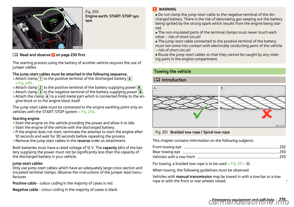
Fig. 251
Braided tow rope / Spiral tow rope
This chapter contains information on the following subjects:
Front towing eye
232
Rear towing eye
233
Vehicles with a tow hitch
233
For towing, a braided tow rope is to be used » Fig. 251 -
.
When towing, the following guidelines must be observed.
Vehicles with manual transmission may be towed in with a tow bar or a tow
rope or with the front or rear wheels raised.
231Emergency equipment and self-help
Page 249 of 276

Maximum permissible front axle load
Maximum permissible rear axle load
Vehicle identification number (VIN)
The vehicle identification number - VIN (vehicle body number) is stamped into
the engine compartment on the right hand suspension strut dome. This num-
ber is also located on a sign on the lower left hand edge below the windscreen
(together with a VIN bar code), and on the type plate.
The VIN number can also be displayed in the Infotainment » Owner´s Manual
Infotainment , chapter CAR - vehicle settings .
Engine number
The engine number (three-digit identifier and serial number) is stamped on the
engine block.
Supplementary Information (applies to Russia)
The full type approval number of the means of transport is indicated in the
registration documents, field 17.
Maximum permissible towed weight
The listed maximum allowable trailer weight is only valid for altitudes up to
1000 m above sea level.
The engine output falls as altitude increases, as does the vehicle's climbing
power. Therefore, for every additional 1000 m in height (or part), the maximum
permissible towed weight must be reduced by 10%.
The towed weight is made up of the actual weights of the loaded towing vehi-
cle and the loaded trailer.WARNINGDo not exceed the specified maximum permissible weights – risk of acci-
dent and damage!
Operating weight
This value represents the minimum operating weight without additional
weight-increasing equipment such as air conditioning system or spare wheel.
The specified operating weight is for orientation purposes only.
The operating weight also contains the weight of the driver (75 kg), the weight
of the operating fluids, the tool kit, and a fuel tank filled to 90 % capacity.
1011Operating weight - SuperbEngineTransmissionOperating weight (kg)1.4 l/92 kW TSIMG1375
1.4 l/110 kW TSI ACT
MG1395MG 4x41505DSG14251.4 l/110 kW TSIMG1388DSG14181.8 l/132 kW TSIMG1465DSG14852.0 l/162 kW TSIDSG (EU6)1505DSG (EU4)15002.0 l/206 kW TSIDSG 4x41615
1.6 l/88 kW TDI CR
MG1465MG (Green Line)1485DSG1480
2.0 l/110 kW TDI CR
MG1485MG 4x41605DSG15002.0 l/130 kW TDI CRDSG1515
2.0 l/140 kW TDI CR
MG1505DSG1555DSG 4x41615
Operating weight - Superb Estate
EngineTransmissionOperating weight (kg)1.4 l/92 kW TSIMG1395
1.4 l/110 kW TSI ACT
MG1415MG 4x41525DSG14451.4 l/110 kW TSIMG1408DSG1438 247Technical data