2015 SKODA RAPID SPACEBACK radio
[x] Cancel search: radioPage 20 of 208

WARNING (Continued)■The installation of impermissible accessories in the vicinity of the head
airbags can considerably impair the protection offered by the head airbag in
the event of it being deployed. When the deployed head airbag is inflated,
parts of the accessories fitted could be thrown into the interior of the car
and injure the occupants » page 130.■
When objects are attached to the sun visor, the visor can not be pivoted
to the side windows. This might result in injuries to the occupants if the
head airbag is deployed.
■
There must not be any further persons, animals or objects positioned be-
tween the occupants and the deployment area of the airbag. In addition,
none of the occupants should lean their head out of the window when driv-
ing, or extend their arms and hands out of the window.
Note
In vehicles with head airbags, the lettering can be seen on the B column
cladding.
Deactivating airbags
Introduction
This chapter contains information on the following subjects:
Deactivating airbags
18
Deactivating the front passenger airbag
18
Deactivating airbags
If you sell your vehicle, provide the complete vehicle documentation to the
new owner. Please note that the information relating to the possibility of de-
activating the front passenger airbag must be included!
If an airbag in the vehicle is to be turned off, then the buyer is to draw atten-
tion to this fact!
Deactivating an airbag should be considered in cases such as the ones below. ▶ If a rear-facing child seat must be used on the front passenger seat
» page 19 , Transporting children safely .
▶ If it is not possible to maintain a distance of at least 25 cm between the mid-
dle of the steering wheel and chest, despite the driver's seat being correctly
adjusted.
▶ If special attachments are required in the area of the steering wheel because
of a physical disability.
▶ If different seats have been fitted (e.g. orthopaedic seats without side air-
bags).
The front passenger airbag can be switched off with the key-operated switch
» Fig. 12 on page 18 -
.
We recommend that you ask a ŠKODA service partner to deactivate any other
airbags.
Deactivation indicator
Display of the airbag deactivation » page 34,
Airbag system .
Note
A ŠKODA service partner will be able to inform you which, if any, of your vehi-
cle's airbags can or must be deactivated.
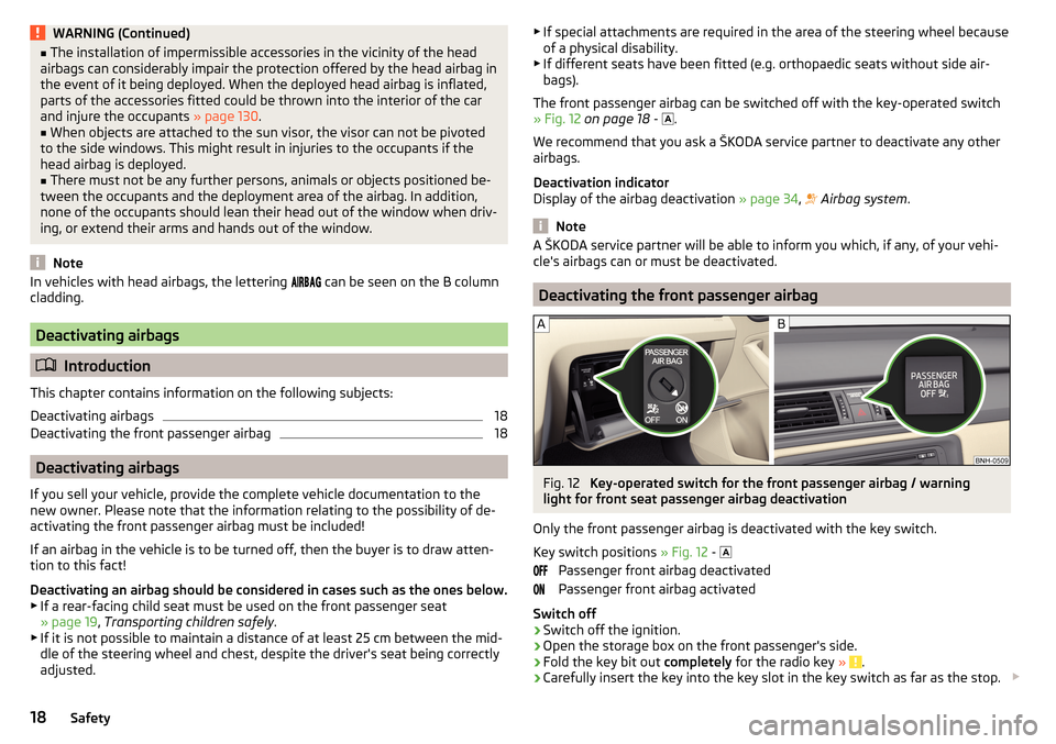
Deactivating the front passenger airbag
Fig. 12
Key-operated switch for the front passenger airbag / warning
light for front seat passenger airbag deactivation
Only the front passenger airbag is deactivated with the key switch.
Key switch positions » Fig. 12 -
Passenger front airbag deactivated
Passenger front airbag activated
Switch off
›
Switch off the ignition.
›
Open the storage box on the front passenger's side.
›
Fold the key bit out completely for the radio key » .
›
Carefully insert the key into the key slot in the key switch as far as the stop.
18Safety
Page 21 of 208

›Use the key to turn the slot of the key switch
» Fig. 12 carefully into the
position .›
Pull the key out of the slot in the key switch » .
›
Close the storage box on the front passenger's side.
›
Check that the warning light
1)
under the text
» Fig. 12 -
lights up after the ignition is switched on.
Switching on
›
Switch off the ignition.
›
Open the storage box on the front passenger's side.
›
Fold the key bit out completely for the radio key » .
›
Carefully insert the key into the key slot in the key switch as far as the stop.
›
Use the key to turn the slot of the key switch » Fig. 12
carefully into the
position .
›
Pull the key out of the slot in the key switch
» .
›
Close the storage box on the front passenger's side.
›
Check that the warning light
under the text
» Fig. 12
-
does not illuminate after the ignition is switched on.
WARNING■ The driver is responsible for whether the airbag is switched on or switch-
ed off.■
Only switch off the airbag when the ignition is switched off! Otherwise a
fault can occur in the system for deactivating the airbag.
■
If the
warning light is flashing, the front passenger airbag will not
be deployed in an accident! Have the airbag system checked by a specialist
garage immediately.
■
Do not leave the key inserted in the key-operated switch while driving -
vibrations can cause the key to turn in the slot and switch on the airbag!
The airbag could be triggered unexpectedly in an accident - it may result in
injury or death!
CAUTION
An insufficiently folded out key bit can damage the key switch!Transporting children safely
Child seat
Introduction
This chapter contains information on the following subjects:
Use of a child seat on the front passenger seat
20
Use of the child seat in the front passenger seat
21
Child safety and side airbag
21
Classification of child seats
21
Use of child seats fastened with a seat belt
21
To avoid serious injury or death children are always to be in an appropriate
child safety seat with regards to height, weight, and age.
For safety reasons, we recommend that you always transport child seats on the rear seats.
Child seats complying with the ECE-R 44 Economic Commission for Europe
standard must be used.
Child seats that comply with the ECE-R 44 standard are identified with a test
mark that cannot be removed: a capital E in a circle, with the test number be-
low.
With child safety seats in groups 2 and 3, make sure that the loop-around fit-
tings attached to the child seat headrest is positioned in front of or at the
same height as the loop-around fittings on the B pillar on the passenger side.
WARNING■ One should never carry children, and also not babies! - on one's lap.■Never leave children unattended in the vehicle. Certain outside climatic
conditions can cause life-threatening temperatures in the vehicle.■
The child must be secured in the vehicle during the entire journey! Other-
wise, the child would be thrown through the vehicle in the event of an acci-
dent, causing fatal injuries to both the child and other occupants.
1)
The warning light
comes on for a few seconds after the ignition is switched on, goes out for about
1 second and then comes on again.
19Transporting children safely
Page 45 of 208

›Press and hold the dial G on the multifunction steering wheel
» Fig. 31 on
page 43 .
Main menu items (depending on vehicle equipment) ■Driving data
» page 40
■
Assist systems
» page 45
■
Navigation
» page 44
■
Audio
» page 44
■
Telephone
» page 45 ;
■
Vehicle
» page 39 , Auto-check control
The menus can be opened using the buttons on the control lever » Fig. 30 on
page 43 or on the multi-function steering wheel » Fig. 31 on page 43 .
Note
■
If warning messages are displayed, these messages must first be confirmed
to access the main menu.■
The travel mode can be set in the Infotainment » Owner´s Manual Infotain-
ment , chapter Vehicle settings (SET-UP button) .
■
For vehicles without Infotainment, the display language can only be adjusted
by a specialist garage.
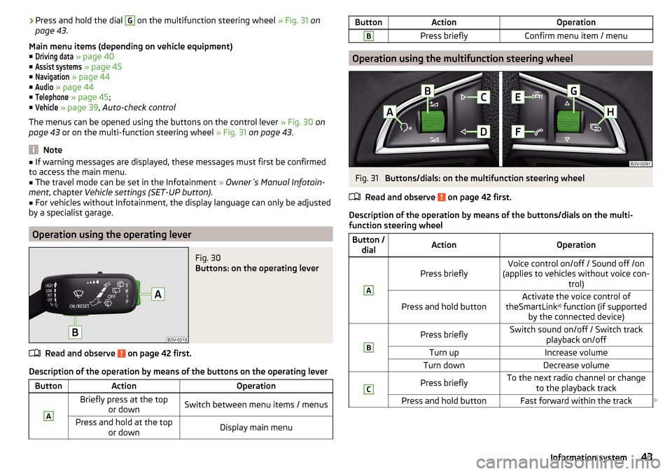
Operation using the operating lever
Fig. 30
Buttons: on the operating lever
Read and observe on page 42 first.
Description of the operation by means of the buttons on the operating lever
ButtonActionOperationABriefly press at the top or downSwitch between menu items / menusPress and hold at the top or downDisplay main menuButtonActionOperationBPress brieflyConfirm menu item / menu
Operation using the multifunction steering wheel
Fig. 31
Buttons/dials: on the multifunction steering wheel
Read and observe
on page 42 first.
Description of the operation by means of the buttons/dials on the multi-
function steering wheel
Button / dialActionOperationA
Press brieflyVoice control on/off / Sound off /on
(applies to vehicles without voice con- trol)Press and hold buttonActivate the voice control of
theSmartLink a)
function (if supported
by the connected device)BPress brieflySwitch sound on/off / Switch track playback on/offTurn upIncrease volumeTurn downDecrease volumeCPress brieflyTo the next radio channel or changeto the playback trackPress and hold buttonFast forward within the track 43Information system
Page 46 of 208

Button /dialActionOperationDPress brieflyto the previous radio channel orchange to the playback track b)Press and hold buttonFast reverse within the trackEPress brieflySelect menu item Assist systems
» page 45
F
Press brieflyTake the call / end the call / Menu Tel-ephone
display / display call list / call
the selected contactPress and hold buttonReject call / Redial last callG
Press brieflyConfirm menu item / menu / Repeat
the last navigation announcement or clarify / interrupt traffic report
Turn up
Previous menu item / track b)
/ Show
available list (e.g. list of available
channels, list of the last destinations, call list)Turn downNext menu item / track / View availa-
ble list (e.g. List of available channels, list the last destinations, call list)HPress brieflyReturn to a previous level in the menuPress and hold buttonDisplay main menua)
» Infotainment Owner's Manual
b)
Valid for pressing within about 4 s from the beginning of the given track. Pressing after about 4 seconds
from the beginning of the track, starts the playback from the beginning of the track.
Note
Depending on equipment not all functions may be available. The system can
indicate this fact by a text message in the display of the instrument cluster or
in the Infotainment display.
Menu item
Navigation
Read and observe on page 42 first.
Select menu item
Navigation›
Select and confirm
Navigation
in the main menu.
Route guidance takes place
Graphical driving recommendations and other route and destination informa-
tion are displayed after selection.
No route guidance is carried out
A compass/vehicle symbol is shown to display the current vehicle position in relation to the compass after selection.
Then turn dial G
» Fig. 31 on page 43 on the multifunction steering wheel to
display the
Last destinations
menu.
The menu shows the
Home address
menu item and a list of recent destinations.
When you select one of the menu items, the destination name and the follow-
ing items are displayed.
■
OK
- Start navigation
■
Cancel
- Return to the Navigation menu – the compass/vehicle symbol will be
displayed
If the home address is not defined when the menu item
Home address
is selec-
ted, the following message appears:
Please enter the home address on the infotain-ment system.
Menu item
Audio
Read and observe on page 42 first.
Select menu item
Audio›
Select and confirm
Audio
in the main menu.
The following information can be displayed in the display.
■ Radio
■ Currently played station (name/frequency):
■ The selected frequency range (e.g. FM) optionally with the number of the
station button (e.g. FM3), if the station is stored in the memory list
■ List of available station (if more than 5 stations can be received);
■ TP traffic announcements.
■ Media
■ Name of the track being played, if necessary, further information regarding
title (e.g. artist, album name), if this information is stored as a so called ID3
tag on the audio source.
44Using the system
Page 54 of 208

The locking is shown by the illuminated symbol .
The central locking system also operates if the ignition is switched off.
The following applies after locking. ▶ Opening the doors and the boot lid from the outside is not possible.
▶ The doors can be unlocked and opened from the inside by a single pull on the
opening lever of the respective door.WARNINGDoors locked from the inside make it difficult for rescuers to get into the
vehicle in an emergency – risk to life!
Safe securing system
Read and observe
and on page 50 first.
As soon as the vehicle is locked from the outside, the safe lock prevents open-
ing the doors from the inside.
This function is pointed out by the following message on the display of the in-
strument cluster after switching out the ignition.
Check SAFELOCK! Owner's manual!CHECK SAFELOCK
After locking the vehicle, the warning light in the driver's door flashes for
around 2 seconds in quick succession, afterwards it begins to flash evenly at
longer intervals.
Switching off
The safe lock can be switched off in one of the following ways.
▶ By locking twice within 2 seconds.
▶ By disabling the button for interior monitoring and anti-towing » page 54.
The indicator light in the driver door flashes for about 2 seconds fast, goes out
and starts to flash at longer intervals after about 30 seconds.
If the vehicle is locked and the safe securing system is switched off, the door
can be opened separately from the inside by a single pull on opening lever.
The SafeLock switches on the next time the vehicle is locked.
WARNINGIf the car is locked and the safe securing system activated, no people must
remain in the car as it will then not be possible to either unlock a door or
open a window from the inside. The locked doors make it more difficult for
rescuers to get into the vehicle in an emergency – risk to life!
Individual settings
Read and observe
and on page 50 first.
The following functions of the central locking can be set in the Infotainment
» Owner´s Manual Infotainment , chapter CAR - Vehicle Settings or be set by a
specialist company.
Opening a single door
The function allows you to unlock only the driver's door and the fuel filler flap
with the radio remote control. KESSY makes possible the release of individual
doors as well as the fuel filler flap, depending on the area in which the key is
located. The other doors and the boot lid are only unlocked when the unlock-
ing is repeated.
Unlocking a vehicle side door
This function enables you to unlock both doors on the driver's side and the
fuel filler flap with the radio remote control unit. KESSY makes possible the re-
lease of both doors on one side as well as the fuel filler flap, depending on the
area in which the key is located. The other doors and the boot lid are only un-
locked when the unlocking is repeated.
Unlock all doors
The function allows you to unlock all doors, the boot lid and the fuel filler flap.
Automatic locking/unlocking
This function allows you to lock all doors and the boot lid from a speed of
about 15 km/h. The button in the handle of the boot lid is deactivated.
Renewed automatic unlocking of all doors as well as the luggage compartment
door when removing the ignition key or by opening any of the doors. In vehi-
cles with the system KESSY this is when any door is opened.
The vehicle can also be unlocked by pressing the central locking button
» page 51 .
52Using the system
Page 64 of 208

Switching off takes place in reverse order.
If the vehicle is not fitted with front fog lights, the rear fog light is switched on
by pulling out the light switch to the only possible setting.
Note
While driving with an accessory connected to the trailer socket (e.g. trailer,
bike carrier) only the equipment is illuminated by the fog light. The towing de-
vice must be installed at the factory or from the ŠKODA original accessories.
Fog lights with the CORNER function
Read and observe
on page 59 first.
The function CORNER provides better illumination of the nearby environmentwhen turning, manoeuvring or anything similar.
The function automatically switches on the fog lights on each side of the ve- hicle, if the following conditions are met.
The turn signal is switched on or the front wheels are turned sharply 1)
.
The vehicle speed is below 40 km/h.
The low beam is switched on.
The fog lights are not switched on.
Note
The two fog lights are switched on when you shift into the reverse gear.
COMING HOME / LEAVING HOME
Read and observe
on page 59 first.
The function COMING HOME ensures that the vehicle's environment is illumi-
nated after switching off the ignition and opening the driver's door.
The function LEAVING HOME ensures that the vehicle's environment is illumi-
nated after unlocking the vehicle with the radio remote control unit.
The function switches the light on only if there is poorer visibility and the light
switch is in the position
.
Enabling / disabling and setting functions
The functions and setting of the lighting duration can be activated or deactiva-
ted in the Infotainment system » Owner´s Manual Infotainment , chap-
ter CARVehicle settings .
CAUTION
■
Poorer visibility is detected by a sensor mounted below the windscreen in
the holder of the inside mirror or in the control panel. Do not attach any stick-
ers or similar objects in front of the sensor in order to avoid impairing the func-
tion or its reliability.■
If this option is always enabled, then the battery is heavily loaded.
Hazard warning light system
Fig. 50
Button for hazard warning light
system
Read and observe on page 59 first.
The hazard warning lights make other road users aware of your vehicle.
The function switches on all indicators.
Switching on/off
›
Press the button
» Fig. 50 .
When you turn it on the warning light
flashes in the button and at the same
time the warning lights
in the instrument cluster.
The hazard warning light system can also be operated if the ignition is switch-
ed off.
If one of the airbags is deployed, the hazard warning light system will switch
on automatically.
1)
If both switch-on conditions are conflicting, for example, if the front wheels are turned to the left and
the right turn signal light is switched on, the turn signal light has the higher priority.
62Using the system
Page 153 of 208

WARNINGThere is risk of injuries, poisoning, chemical burns, explosions or fire when
working on the battery and on the electrical system. It is essential to com-
ply with the general applicable safety rules as well as the warning instruc-
tions outlined below.■
Keep the vehicle battery away from people who are not completely inde-
pendent, especially children.
■
Do not tilt the battery otherwise battery electrolyte may flow out of the
battery vent openings.
■
Protect your eyes by wearing safety goggles or a face shield – risk of
blindness!
■
Always wear protective gloves, eye and skin protection when handling
the vehicle battery.
■
The battery acid is strongly corrosive and must, therefore, be handled
with the greatest of care.
■
Corrosive fumes in the air irritate the air passages and lead to conjunctivi-
tis and inflammation of the air passages in the lungs.
■
Battery acid corrodes dental enamel and, if it comes into contact with the
skin, causes deep wounds that take a long time to heal.
■
If any battery acid comes into contact with your eyes, rinse the affected
eye immediately with clean water for several minutes and consult a doctor
immediately!
■
Splashes of acid on your skin or clothes should be neutralised as soon as
possible using soap suds and then rinsed with plenty of water.
■
If you swallow battery acid, consult a doctor immediately!
WARNING■ The use of open flames and light should be avoided.■Smoking and radio triggering activities should be avoided.■
Never use a damaged vehicle battery – risk of explosion!
■
Never charge a frozen or thawed vehicle battery – risk of explosion and
chemical burns!
■
Replace a frozen vehicle battery.
■
Never jump-start vehicle batteries with insufficient acid levels – risk of
explosion and chemical burns.
CAUTION
■ Improper handling of the vehicle battery may cause damage.■Ensure that battery acid does not come into contact with the bodywork – risk
of damage to the paintwork.■ If the vehicle has not been driven for more than 3-4 weeks, the battery will
discharge. Prevent the battery from discharging by disconnecting the battery's
negative terminal
or continuously charging the battery with a very low
charging current.■
Do not place the battery in direct daylight in order to protect the vehicle bat-
tery housing from the effects of ultra-violet light.
■
If the vehicle is frequently used for making short trips, the vehicle battery
will not have time to charge up sufficiently and may discharge.
Note
■ We recommend having all work on the vehicle battery carried out by a spe-
cialist garage.■
You should replace batteries older than 5 years.
Opening the cover
Fig. 157
Battery cover
Read and observe and on page 151 first.
The battery is located in the engine compartment.
›
Open the cover in the direction of the arrow.
The battery cover is installed in reverse order.
151Inspecting and replenishing
Page 177 of 208

CAUTION■“Never repair” fuses, and do not replace them with fuses of a higher amper-
age – risk of fire! This may also cause damage at other points in the electrical
system.■
If a newly inserted fuse blows again after a short time, have the electrical
system checked as quickly as possible by a specialist garage.
■
A blown fuse is recognisable by the molten metal strip. Replace the faulty
fuse with a new one of the same amperage.
Note
■
We recommend always carrying replacement fuses in the vehicle. A box of
replacement fuses and bulbs can be purchased from ŠKODA Genuine Accesso-
ries.■
There can be several power-consuming devices for one fuse.
■
Multiple fuses may exist for a single power-consuming device.
Fuses in the dash panel
Fig. 183
Remove the fuse box cover.
Read and observe and on page 174 first.
The fuses are located on the bottom of the dash panel behind a cover.
Replacing fuses
›
Grip the fuse box cover at point
A
and take-out in the direction of arrow
» Fig. 183 .
›
Remove the plastic clip from the holder in the fuse box cover.
›
Place the clip on the respective fuse and pull this fuse out.
›
Insert a new fuse.
›
Replace the bracket at the original position.
›
Insert the top edge of the cover into the dash panel first.
Carefully push the cover in.
Assignment of the fuses in the dash panelFig. 184
Schematic representation of the fuse box for vehicles with left-
hand steering/right-hand steering
Read and observe
and on page 174 first.
No.Power consumer1Left light2Central locking system3Relay for ignition4Right light5Power windows - driver6Central control unit - interior lights7Horn8Towing hitch - left light
9
Operating lever beneath the steering wheel, engine control unit (on-
ly without KESSY), automatic gearbox (only without KESSY), selector
lever of the automatic transmission (only without KESSY), ESC (only
without KESSY), towing equipment (only without KESSY), power
steering (only without KESSY)10Power windows - rear left11Headlight cleaning system12Radio, navigation display13Taxi preparation14Operating lever under the steering wheel, light switch, ignition key
removal lock (automatic gearbox), headlight flasher, SmartGate, rain
sensor 175Fuses and light bulbs