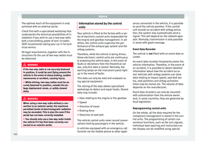
Page 81 of 232

Fuses and bulbs
Additional bulb specifications
The s pec
ific
ations of some headlamp bulbs
and bulbs for the rear lamps fitted at the fac-
tory may be different to those of conventional
bulbs. Bulb information is displayed on the
bulb socket or on the bulb itself. WARNING
If the road is not well-lit and the vehicle is
not c l
early visible to other drivers, there is a
risk of accident. WARNING
Failure to replace bulbs correctly may cause
serious ac
cidents.
● Before carrying out any work in the engine
compar
tment please read and observe the
warnings ››› page 184. In any vehicle, the en-
gine compartment is a hazardous area and
could cause severe injury.
● The bulbs H4, HB4 and H7 are pressurised
and might exp
lode on changing them.
● Only replace the bulbs concerned when
they hav
e cooled.
● Never replace bulbs alone if you are not fa-
miliar w
ith the operations necessary. If you
are not sure about procedures then visit a
specialised workshop to carry out the neces-
sary work.
● Never touch the bulb glass directly. Finger-
prints w
ill be evaporated by the heat of the operating bulb thus “fogging” up the reflec-
tor
.
● The he
adlamp frameworks in the engine
compar
tment and the rear lamps contain
sharp elements. Always protect your hands
when changing bulbs. CAUTION
● Af ter c
hanging a bulb, if the rubber covers
are not replaced correctly on the headlamp
framework, the electrical installation may be
damaged, especially if water is allowed to en-
ter.
● Remove the ignition key before working on
the electric sy
stem. Otherwise, a short circuit
could occur.
● Switch off the lights and the parking light
before c
hanging a bulb.
● Take good care to avoid damaging any com-
ponents. Replacing the bulbs in the headlights
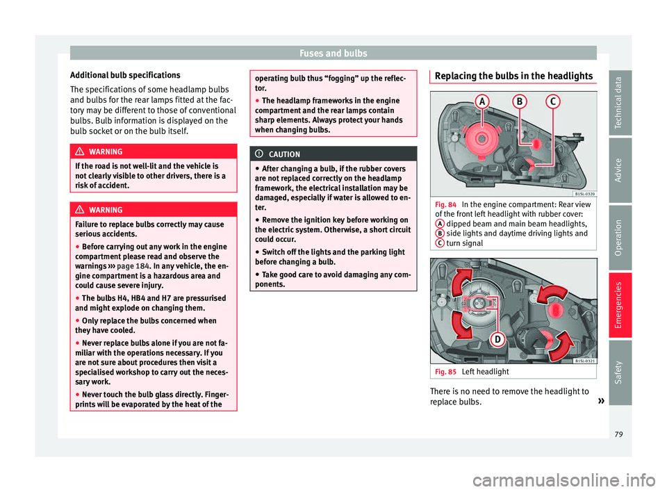
Fig. 84
In the engine compartment: Rear view
of the fr
ont
left headlight with rubber cover:
A dipped beam and main beam headlights,
B side lights and daytime driving lights and
C turn signal
Fig. 85
Left headlight There is no need to remove the headlight to
r
ep l
ace bulbs. »
79
Technical data
Advice
Operation
Emergencies
Safety
Page 82 of 232

Emergencies
Complete operations only in the sequence
giv en:Dipped beam and main beam headlights
Fig. 84
A
1.Open the bonnet ››› page 184.
2.
Remove the bulb connector H4. Remove the rub-
ber cover using the tabs.
Press the retaining clip ››› Fig. 85 D downwards
in the direction of the arrow, unclip sideways, and
remove it.
3.Remove the bulb from the holder. If necessary,
press the lock on the bulb holder.
4.Replace the faulty bulb with a new identical bulb.
5.Insert the bulb, return it to its position and insert
the retaining clip ››› Fig. 85 D
6.Place the rubber cover and check that is in the
correct position. Insert the connector to the bulb
H4.
Side light and daytime lights
Fig. 84 B /
Front turn indicator Fig. 84 C
1.Open the bonnet
››› page 184.
2.Turn the bulb holder in an anticlockwise direction
as far as it will go and remove it, along with the
bulb, pulling backwards.
3.Remove the bulb from the holder. If necessary,
press the lock on the bulb holder.
4.Replace the faulty bulb with a new identical bulb.
Side light and daytime lights Fig. 84 B /
Front turn indicator Fig. 84 C
5.Insert the bulb holder in the headlight and turn it
clockwise as far as the stop. Note
The images show the left hand headlight
from behind. The s
tructure of the right hand
side headlight is symmetric. Replacing the front bumper bulbs
Fig. 86
In the front right wheel arch: Remove
the r et
ainin
g screws (arrows) and take out the
expansive rivet A . Fig. 87
Changing the bulbs in the headlights
Complete operations only in the sequence giv-
en:
1.Unscrew the 2 retaining screws of the wheel arch
trim ››› Fig. 86 (arrows) with the screwdriver from
the vehicle took kit ››› page 69.
2.
Unscrew the expansive rivet in the lower front part
of the wheel arch trim A with the screwdriver
from the vehicle tool kit and completely remove it
››› page 69.
3.Carefully fold the wheel arch trim to the side.
4.Release the connector ››› Fig. 87 1 and remove
it.
5.
Turn the bulb holder ››› Fig. 87 in the direction of
the arrow, in an anticlockwise direction as far as it
will go and remove it, along with the bulb, pulling
backwards.
6.Replace the faulty bulb with a new identical bulb. 80
Page 83 of 232

Fuses and bulbsComplete operations only in the sequence giv-
en:
7.Insert the bulb holder in the headlight and turn it
clockwise as far as the stop.
8.Plug the connector
1 into the bulb holder. The
connector must audibly click into place.
9.Replace the wheel arch trim into its position.
10.Place the expansive rivet in the wheel arch trim
and bumper and press it completely inwards
››› Fig. 86 A
.
11.Securely screw the 2 retaining screws
››› Fig. 86
(arrows) with a screwdriver. Changing the bulbs in the rear lights
Fig. 88
On the side of the luggage compart-
ment: A: R emo
v
e the cover, B: Removing the
tail light units Fig. 89
Tail light unit: C: Remove the bulb
ho l
der
, D: Remove the bulbs. Complete operations only in the sequence
giv
en.
R emo
ving the rear light units
1.Open the rear lid ››› page 97.
2.Carefully remove the cover 1 towards the lever
››› Fig. 88 A.
3.Pull the release 3 in the connector 2 in the di-
rection of the arrow ››› Fig. 88 B. Use the screwdriv-
er in the vehicle tool kit.
4.Press position 4 and remove the connector 2›››
Fig. 88 B.» 81
Technical data
Advice
Operation
Emergencies
Safety
Page 84 of 232

Emergencies5.Unscrew the wing nut
5
››› Fig. 88 B.
6.Remove the tail light from the bodywork by careful-
ly pulling backwards.
7.Disassemble the tail light unit and place it on a
flat, clean surface. To change the bulb
8.Unlock the bulb holder locking tab (arrow)
››› Fig. 89 C and remove the bulb holder from the
tail light.
9.Replace the faulty bulb by a new identical bulb
››› Fig. 89 D.
10.Place the bulb holder in the tail light unit. The at-
tachment tabs (arrow) should audibly click into
place ››› Fig. 89 C. Assembling the rear light units
11.Carefully insert the tail light unit into the opening
in the bodywork.
12.Support the tail light with one hand in the assem-
bly position and securely screw the wing nut with
the other
5
››› Fig. 88 B.
13.Ensure that the tail light unit has been correctly
fitted and is firmly secured.
14.Insert the connector 2 into the bulb holder and
press the lock 3 on the connector in the oppo-
site direction to the arrow ››› Fig. 88 B.
15.Insert the cover. The cover should lock into place.
16.Close the rear lid ››› page 97. Changing the number plate light
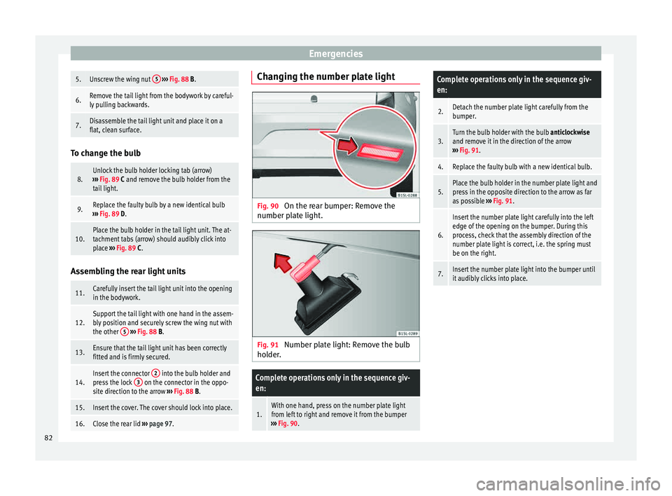
Fig. 90
On the rear bumper: Remove the
number p l
at
e light. Fig. 91
Number plate light: Remove the bulb
ho lder
.
Complete operations only in the sequence giv-
en:
1.With one hand, press on the number plate light
from left to right and remove it from the bumper
››› Fig. 90.
Complete operations only in the sequence giv-
en:
2.Detach the number plate light carefully from the
bumper.
3.Turn the bulb holder with the bulb anticlockwise
and remove it in the direction of the arrow
››› Fig. 91.
4.Replace the faulty bulb with a new identical bulb.
5.Place the bulb holder in the number plate light and
press in the opposite direction to the arrow as far
as possible ››› Fig. 91.
6.
Insert the number plate light carefully into the left
edge of the opening on the bumper. During this
process, check that the assembly direction of the
number plate light is correct, i.e. the spring must
be on the right.
7.Insert the number plate light into the bumper until
it audibly clicks into place. 82
Page 85 of 232
Fuses and bulbs
Changing the side turn signal bulb Fig. 92
Removing the side turn signal Fig. 93
Side turn signal: Changing the bulbs.Complete operations only in the sequence giv-
en:
1.With one hand move the side turn signal back-
wards ››› Fig. 92 1.
2.Remove the side turn signal from the chassis by
leverage 2.
Complete operations only in the sequence giv-
en:
3.Remove the bulb holder with the bulb in the direc-
tion of the arrow
››› Fig. 93 1.
4.Remove the bulb holder bulb in a straight direc-
tion.
5.Replace the faulty bulb with a new identical bulb.
6.Install the bulb holder.
7.
Place the side turn signal on the chassis on the
side situated towards the rear of the vehicle until
the spring clicks into the other side of the side turn
signal. 83
Technical data
Advice
Operation
Emergencies
Safety
Page 86 of 232
Operation
Fig. 94
Dash panel84
Page 87 of 232

General instrument panel
Operation
Gener a
l
instrument panel
Instrument panel Key to
Fig. 94:
Interior door r el
ease lever . . . . . . . . . 96
Turn switch for adjusting the exteri-
or mirrors . . . . . . . . . . . . . . . . . . . . . . . . 107
– Exterior mirr or a
djustment
– Heated exterior mirrors
Air outlets . . . . . . . . . . . . . . . . . . . . . . . . 124
Lever for . . . . . . . . . . . . . . . . . . . . . . . . . 101
– Turn sign
als and main beam
headlights
– Cruise control system (CCS) –
– – /+ – /- . . . . . . .151
Steering wheel with horn and – Driver airb ag . . . . . . . . . . . . . . . . . . . 14
Da
sh panel . . . . . . . . . . . . . . . . . . . . . . . 86, 25
Windscreen wiper/ windscreen
wash l
ever . . . . . . . . . . . . . . . . . . . . . . . 106
– Wind s
creen wipers
– Rear window wiper
1 2
3
4
5
6
7 –
Lev
er w
ith buttons for controlling
the SEAT information system - ,
/ . . . . . . . . . . . . . . . . . . . . . . . . . 23
Controls for:
– Start
-Stop system button . . .156
– Rear w
indow heating button . .124
– Left
seat heating controls . . . . . 109
Switches for: – Heating and
ventilation system .124
– Air conditioner . . . . . . . . . . . . . . . . . . 124
SEA
T Portable System (supplied by
SEAT) . . . . . . . . . . . . . . . . . . . . . . . . . . . . 164
R
adio (factory fitted) ›››
Booklet Ra-
dio
Controls for:
– Hazard warning lights switch
. . . . . . . . . . . . . . . . . . . . . . . . . . . . . . 69
– Pa s
senger front airbag off warn-
ing lamp . .58
– Right seat
heating controls
or rear window heating button
(alternative position) . . . . . . . . . . .109, 124
Storage compartment with drink
hol der in the c
entre console . . . . . . .116
Handle of the storage compartment
or stor
age compartment open 1)
. . . 112
8 9
10
11
12
13
14 In the side of the dash panel: Key
sw
it
c
h for switching off the front
passenger airbag 1)
. . . . . . . . . . . . . . . 58
Position of passenger front airbag
on the dash p
anel . . . . . . . . . . . . . . . . 58
Ashtray* . . . . . . . . . . . . . . . . . . . . . . . . . 116
12 volt socket or cigarette light-
er* . . . . . . . . . . . . . . . . . . . . . . . . . . . . . . . 117, 116
Lever for:
– Manual g
earbox . . . . . . . . . . . . . . . . 138
– Autom atic
gearbox . . . . . . . . . . . . . 139
Handbrake . . . . . . . . . . . . . . . . . . . . . . . 132
Button for:
– City
Safety Assist function
. . . . . . . . . . . . . . . . . . . . . . . . . . . 152
Ignition lock . . . . . . . . . . . . . . . . . . . . . . 130
Pedals . . . . . . . . . . . . . . . . . . . . . . . . . . . 137
Storage compartment . . . . . . . . . . . . .112
Steering column adjustment lev-
er . . . . . . . . . . . . . . . . . . . . . . . . . . . . . . . . 47
Open bonnet lever . . . . . . . . . . . . . . . . 184
Headlight range control . . . . . . . . 101
Light switch . . . . . . . . . . . . . . . . . . . 101
Central lock button . . . . . . . . . .92
Button for operating the electric
window
s of the driver door . . . . .99
15 16
17
18
19
20
21
22
23
24
25
26
27
28
29
30
1)
According to version
85
Technical data
Advice
Operation
Emergencies
Safety
Page 88 of 232

Operation
Instruments V iew of
in
strument panelFig. 95
Instrument panel, on dash panel: variant 1 (A) and variant 2 (B). Details of the instruments
››
›
Fig. 95:
Speedometer. Depending on the
vehicle in km/h or in mph.
Displays on the screen . . . . . . . . . . . . 87
Reset knob for trip rec
order (trip).
– Press the button 0.0/SET bri
efly to
sw it
ch the trip odometer and od-
ometer.
1 2
3 –
Pr e
s
s the 0.0/SET for
5 seconds
t
o
r
eset the odometer to zero and,
where necessary, other indicators
on the multifunction display. . . . .23
Fuel reserve display . . . . . . . . . . . . . . . 180
Rev counter (with the engine ru
n-
ning, in thousands of revolutions
per minute).
The beginning of the red zone of
the rev counter indicates the maxi-
4 5 mum speed in any gear after run-
nin
g
-in and w
ith the engine hot.
However, it is advisable to change
up a gear or move the selector lever
to D (or lift your foot off the acceler-
ator) before the needle reaches the
red zone ››› .
C loc
k
set button .
– If necessary, change the time dis-
play by pressing the top and
6
86