2015 Seat Leon Sportstourer lights
[x] Cancel search: lightsPage 227 of 308
Towing bracket device
Trailer towing Wh at
do
you need to bear in mind
when towing a trailer? Your vehicle may be used to tow a trailer
when fitted w
ith the c
orrect equipment.
If you wish to retrofit a towing bracket, con-
sult ››› page 228.
Connectors
Your vehicle is fitted with a 13-pin connector
for the electrical connection between the
trailer and the vehicle.
If the trailer has a 7-pin plug you will need to
use an adapter cable. It is available at any
Technical Service.
Trailer weight/drawbar load
Never exceed the authorised trailer weight. If
you do not load the trailer up to the maxi-
mum permitted trailer weight, you can then
climb correspondingly steeper slopes.
The maximum trailer weights listed are only
applicable for altitudes up to 1000 m above
sea level. With increasing altitude the engine
power and therefore the vehicle climbing
ability are impaired because of the reduced
air density. The maximum trailer weight has
to be reduced accordingly. The weight of the
vehicle and trailer combination must be re- duced by 10% for every further 1000 m (or
par
t
thereof). The gross combination weight
is the actual weight of the laden vehicle plus
the actual weight of the laden trailer. When
possible, operate the trailer with the maxi-
mum permitted drawbar load on the ball joint
of the towing bracket, but do not exceed the
specified limit.
The figures for trailer weights and drawbar
loads that are given on the data plate of the
towing bracket are for certification purposes
only. The correct figures for your specific
model, which may be lower than these fig-
ures for the towing bracket, are given in the
vehicle documentation or in ››› chapter Tech-
nical Data .
Distributing the load
Distribute loads in the trailer so that heavy
objects are as near to the axle as possible.
Loads carried in the trailer must be secured
to prevent them moving.
Tyre pressure
Set tyre pressure to the maximum permissi-
ble pressure shown on the sticker on the in-
side of the fuel tank flap. Set the tyre pres-
sure of the trailer tyres in accordance with the
trailer manufacturer's recommendations. Exterior mirrors
Check whether
you can see enough of the
road behind the trailer with the standard rear
vision mirrors. If this is not the case, you
should have additional exterior mirrors fitted.
Both exterior mirrors should be mounted on
hinged extension brackets. Adjust the mirrors
to give sufficient vision to the rear.
Tow rope
Always use a cable between the vehicle and
the trailer ››› page 226.
Trailer rear lights
The trailer's rear lights should comply with
the statutory safety regulations ››› page 226. WARNING
Never transport people in a trailer. This could
re s
ult in fatal accidents. Note
● To w
ing a trailer places additional demands
on the vehicle. We recommend additional
services between the normal inspection inter-
vals if the vehicle is used frequently for tow-
ing a trailer.
● Find out whether special regulations apply
to to
wing a trailer in your country. 225
Technical data
Advice
Operation
Emergencies
Safety
Page 228 of 308

Operation
Hitching and connecting the trailer Fig. 230
Schematic diagram: assignment of
the pins of the trailer's electrical socket.
Key of the Schematic diagram ››› Fig. 230:
PinMeaning
1Left turn signal
2Rear fog light
3Earth, pins 1, 2, 4 to 8
4Right turn signal
5Rear light, right
6Brake lights
7Rear light, left
8Reverse lights
9Permanent live
10Cable without positive charge
11Earth, pin 10
Key of the Schematic diagram ››› Fig. 230:
PinMeaning
12Unassigned
13Earth, pin 9 Electrical socket for trailer
The v
ehic
le is fitted with a 13-pole power
socket for the electrical connection between
the trailer and the vehicle. If the system de-
tects that a trailer has been connected elec-
trically, the electrical equipment on the trailer
will receive voltage through this connection.
Pin 9 has a permanent live. This powers, for
example, the trailer's interior lighting. Pin 10
is only powered when the engine is running.
The charge wire (pin 10) charges, for exam-
ple, a caravan battery.
Pin 9 and 10 should not be connected to
each other to avoid discharging or damaging
the vehicle's battery.
The earth wires, pin 3, pin 11 and pin 13,
should never be connected to each other to
avoid overloading the electrical system.
If the trailer has a 7-contact connector , you
will need to use an adapter cable. In this case
the function corresponding to pin 10 will not
be available. Trailer maximum electricity consumption
Brake lights (total)84 Watts
Turn signal, on each side42 Watts
Side lights (total)100 Watts
Rear lights (total)42 Watts
Rear fog light42 Watts
Never exceed the values indicated!
Note
● If the r e
ar lights of the trailer are not cor-
rectly connected, the vehicle electronics may
be damaged.
● If the trailer absorbs excessive electric cur-
rent, the v
ehicle electronics may be dam-
aged.
● Never connect the trailer's electric system
directly t
o the electrical connections of the
tail lights or any other power sources. Only
use the connections intended for providing
electric current to the trailer. Ball coupling of towing bracket de-
v
ic
e* The ball coupling is provided with instruc-
tion
s
on fittin
g and removing the ball cou-
pling of the towing bracket.
226
Page 229 of 308
Towing bracket device
WARNING
The towing bracket ball coupling must be
st or
ed securely in the luggage compartment
to prevent them being flung through the vehi-
cle and causing injury. Note
● By l
aw, the ball coupling must be removed
if a trailer is not being towed if it obscures
the number plate. Driving with a trailer
Fig. 231
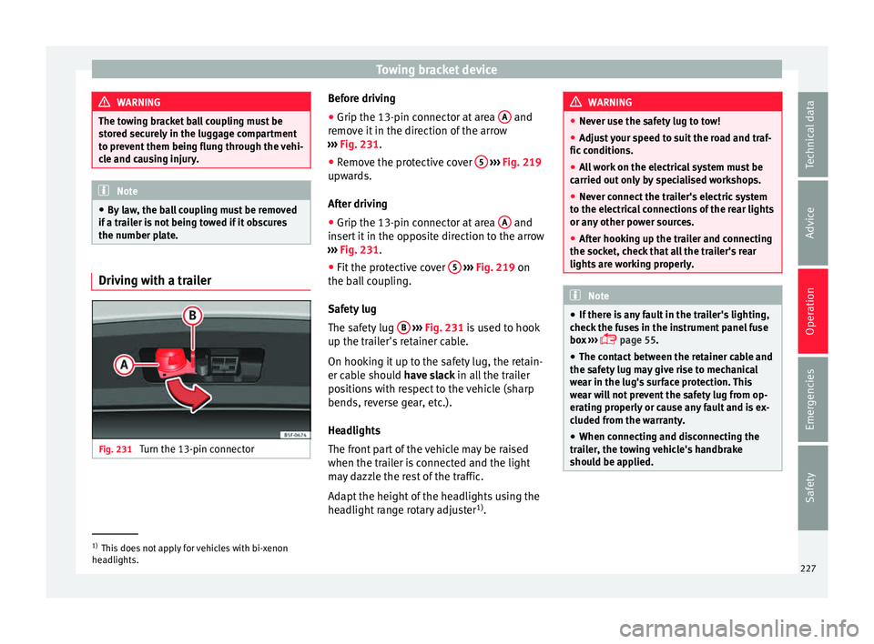
Turn the 13-pin connector Before driving
● Grip the 13-pin connector at area A and
r emo
v
e it in the direction of the arrow
››› Fig. 231.
● Remove the protective cover 5
› ››
Fig. 219
up w
ards.
After driving
● Grip the 13-pin connector at area A and
in ser
t
it in the opposite direction to the arrow
››› Fig. 231.
● Fit the protective cover 5
› ›
› Fig. 219
on
the ball coupling.
Safety lug
The safety lug B
› ›
› Fig. 231
is used to hook
up the trailer's retainer cable.
On hooking it up to the safety lug, the retain-
er cable should have slack in all the trailer
positions with respect to the vehicle (sharp
bends, reverse gear, etc.).
Headlights
The front part of the vehicle may be raised
when the trailer is connected and the light
may dazzle the rest of the traffic.
Adapt the height of the headlights using the
headlight range rotary adjuster 1)
. WARNING
● Never u se the s
afety lug to tow!
● Adjust your speed to suit the road and traf-
fic condition
s.
● All work on the electrical system must be
carried out on
ly by specialised workshops.
● Never connect the trailer's electric system
to the electric
al connections of the rear lights
or any other power sources.
● After hooking up the trailer and connecting
the socket, c
heck that all the trailer's rear
lights are working properly. Note
● If ther e i
s any fault in the trailer's lighting,
check the fuses in the instrument panel fuse
box ›››
page 55.
● The contact between the retainer cable and
the safety
lug may give rise to mechanical
wear in the lug's surface protection. This
wear will not prevent the safety lug from op-
erating properly or cause any fault and is ex-
cluded from the warranty.
● When connecting and disconnecting the
trail
er, the towing vehicle's handbrake
should be applied. 1)
This does not apply for vehicles with bi-xenon
hea dlights.
227
Technical data
Advice
Operation
Emergencies
Safety
Page 230 of 308

Operation
Anti-theft alarm system When the vehicle is locked, the alarm is trig-
ger
ed when the el
ectrical connection be-
tween vehicle and trailer is interrupted.
Always turn off the anti-theft alarm system
before connecting or disconnecting a trailer
››› page 121.
Conditions for the integration of a trailer in
the anti-theft alarm system.
● The vehicle is factory-equipped with an an-
ti-theft al
arm system and a towing bracket
device.
● The trailer is connected electrically to the
tow
ing vehicle by the trailer connector.
● The electrical system of the vehicle and the
trail
er are prepared for operation.
● The vehicle is locked with the ignition key
and the anti-theft al
arm system is activated.CAUTION
For technical reasons, trailers fitted with rear
LED lights ar
e not integrated in the anti-theft
alarm system. Driving tips
Driving with a trailer always requires extra
c
ar e. W
eight distribution
The weight di
stribution of a loaded trailer
with an unladen vehicle is very unfavourable.
However, if this cannot be avoided, drive ex-
tra slowly to allow for the unbalanced weight
distribution.
Speed
The stability of the vehicle and trailer is re-
duced with increasing speed. For this reason,
it is advisable not to drive at the maximum
permissible speed in an unfavourable road,
weather or wind conditions. This applies es-
pecially when driving downhill.
You should always reduce speed immediately
if the trailer shows the slightest sign of snak-
ing. Never try to stop the “snaking” by in-
creasing speed.
Always brake in due course. If the trailer has
an overrun brake, apply the brakes gently at
first and then, firmly. This will prevent the
jerking that can be caused by locking of trail-
er wheels. Select a low gear in due course
before going down a steep downhill. This en-
ables you to use the engine braking to slow
down the vehicle.
Reheating
At very high temperatures and during pro-
longed slopes, driving in a low gear and high
engine speed, always monitor the coolant
temperature gauge ››› page 108. Electronic stability control*
The ESC* sys
tem helps to stabilise the trailer
in case of skidding or rocking.
Retrofitting a towing bracket* Fig. 232
Attachment points for towing brack-
et . 228
Page 234 of 308
Advice
Automatic car washes
B ef
or
e going through a car wash, be sure to
take the usual precautions such as closing
the windows and roof. If the vehicle has spe-
cial accessories such as spoilers or a roof
rack or two-way radio aerial, etc., it is advisa-
ble to consult the car wash tunnel operator.
It is best to use a car wash without revolving
bristles if possible.
Washing the vehicle with a high pressure
cleaner
When washing the vehicle with a high-pres-
sure cleaner, always follow the operating in-
structions for the equipment. This applies
particularly to the operating pressure and the
spraying distance. Do not hold the nozzle too
close to soft materials such as rubber hoses
or seals. The same applies to the parking aid
sensors*, which are located in the rear bump-
er.
Do not use a nozzle that sprays the water out
in a direct stream or one that has a rotating
jet for forcing off dirt.
Washing the car by hand
When washing the car by hand, use plenty of
water to soften the dirt first, and rinse off as
well as possible.
Then clean the vehicle with a soft sponge,
glove or brush using only slight pressure.
You should start on the roof and work down. Special car
soap shou ld only be used for very
persistent dirt.
Rinse the sponge or glove thoroughly and of-
ten.
Wheels, sills and similar should be cleaned
last. Use a second sponge for this. WARNING
● The v ehic
le should only be washed with the
ignition switched off. Failure to follow this in-
struction could result in an accident.
● Do not clean the underside of chassis, the
inside of
wheel arches or wheel trims without
protecting your hands and arms. You may cut
yourself on sharp-edged metal parts. Other-
wise, there is a risk of sustaining cuts.
● When washing the car during the winter
season: w
ater and ice in the brake system
can reduce braking effectiveness: risk of acci-
dent! CAUTION
● Do not w a
sh the vehicle in direct sunlight –
otherwise the paint can be damaged.
● Do not use sponges, abrasive household
spong
es or similar to clean insect remains.
This could damage the surface.
● Clean off stubborn dirt (insects, etc.) from
the headlight
s at regular intervals, for in-
stance when filling the fuel tank. The head-
lights should only be washed with water, do not wipe them with a dry cloth or sponge. It
is
be
st to use soapy water.
● Never wash tyres with a jet that sprays the
water out
in a direct stream. This could dam-
age the tyres even if the spray is kept at a
distance and only used for a very short time.
● Before washing the vehicle in an automatic
car wa
sh, please make sure to retract the ex-
terior mirrors to prevent them from being
damaged. Electrically retractable exterior
mirrors must not be folded in or out by hand,
always use the electrical power control. CAUTION
● Bef or
e washing the vehicle in an automatic
car wash, please proceed as follows to lock
the wiper arms so that they are not moved to-
wards the top of the windscreen:
–the bonnet must be closed.
– switch the ignition on and off.
– press the windscreen wiper lever forward
briefly (windscreen washer function).
This will lock the wiper arms. For the sake of the environment
The car should only be washed in special
wa sh b
ays. These areas are prepared to pre-
vent oily water from getting into the public
drains. In some places, washing vehicles out-
side the areas intended for this purpose is
prohibited. 232
Page 240 of 308

Advice
The retract function may not operate properly
in v
er
y dirty belts. Make sure that the inertia
reel seat belts are completely dry before al-
lowing them to retract. CAUTION
● Do not r emo
ve the seat belts from the vehi-
cle to clean them.
● Do not use chemical cleaning agents on the
seat belt
s, as this can damage the webbing.
Ensure that the seat belts do not come into
contact with corrosive fluids.
● If you find any damage to the belt webbing,
belt fitting
s, the belt retractor or the buckle,
the belt in question must be replaced by a
specialised workshop. Intelligent technology
El ectr
omec
hanical steering Electro-mechanical power steering assists
the driver when s
t
eering.
Electro-mechanical power steering adapts
electronically to the speed of the car, torque
and turning angle.
If the power steering should fail at any time
or the engine is switched off (for instance
when being towed), the car can still be
steered. However, more effort than normal
will be required to turn the steering wheel.
Driver warning lamps and messages (in red) Faulty steering! To
park the vehicle
If the warning lamp remains on and the driver
indication appears, the power steering could
be faulty.
Do not continue driving. Seek specialist as-
sistance. (in yellow) Steering: System
fault! You may continue driving.
If the warning lamp comes on, the steering
could react with more difficultly or more sen-
sitivity than normal. In addition, when driving
in a straight line the steering wheel may be
off-centre. Drive slowly to a specialised workshop and
hav
e the f
ault repaired.
(in yellow) Steering lock:
fault! Go to an Official Service
The electronic steering lock is malfunction-
ing.
Go to a specialised workshop as soon as
possible and have the fault repaired. WARNING
Take it immediately to a specialised work-
shop and hav e the f
ault repaired: risk of acci-
dent! Note
If the lamp (in red) or el se
(in yellow)
lights up briefly, you may continue driving. Progressive steering
Depending on the vehicle equipment, the
pr
ogr
e
ssive steering can adapt steering hard-
ness to the current driving situation. The
power steering only works when the engine
is running.
In city traffic you do not need to turn so much
on parking, manoeuvring or in very tight
turns.
On the road or on the motorway, progressive
steering transmits, for example, in bends, a
238
Page 255 of 308
Checking and refilling levels
CAUTION
● Do not mi x
cleaning products recommen-
ded by SEAT with other products. This could
lead to flocculation and may block the wind-
screen washer jets.
● When topping up service fluids, make abso-
lutely c
ertain that you fill the fluids into the
correct reservoirs. Using the wrong fluids
could cause serious malfunctions and engine
damage!
● Not having windscreen wiper fluid reduces
vis
ibility through the windscreen, and leads
to loss of visibility in headlights in models
with headlight washer. Battery
Gener a
l
informationRead the additional information carefully
› ›
›
page 53.
The battery is located in the engine compart-
ment and is almost maintenance-free. It is
checked as part of the Inspection Service.
Nevertheless, check the terminals are clean
and have the correct tightening torque, espe-
cially in summer and winter.
Disconnecting the battery
The battery should only be disconnected in
exceptional cases. When the battery is dis- connected, some of the vehicle's functions
are “los
t” (››› table on page 253). These
functions will require resetting after the bat-
tery is reconnected.
Deactivate the anti-theft alarm* before you
disconnect the battery Otherwise the alarm
will be triggered.
FunctionReprogramming
One-touch function of
the electric windows››› page 126, One-touch
opening and closing*.
Remote control key
If the vehicle does not re-
spond to the key, they
should be synchronised
››› page 121.
Digital clock››› page 106.
ESC warning lampAfter driving for a few me-
tres, the warning lamp goes
out again. If the vehicle is not used for long periods
The
v
ehic
le has a system for monitoring the
current consumption when the engine is left
unused for long periods of time ››› page 239.
Some functions, such as the interior lights, or
the remote door opening, may be temporarily
disabled to prevent the battery from running
flat. These functions will come back on as
soon as the ignition is switched on and the
engine started. Winter conditions
During the w
inter, the starting power may be
reduced, and if necessary, the battery should
be charged ››› in Important safety warn-
in g
s
for handling a vehicle battery on
page 254
Important safety warnings for han-
dling a v
ehicle battery All work on batteries requires specialist
kno
wl
edg
e. Please refer to a SEAT Official
Service or a workshop specialising in batter-
ies: risk of burns or exploding battery!
The battery must not be opened. Never try to
change the fluid level of the battery. Other-
wise explosive gas is released from the bat-
tery that could cause an explosion.
Wear eye protection.
Battery acid is very corrosive and caustic. Wear
protective gloves and eye protection. In the event
of electrolyte splashes, rinse off with plenty of
water.
Fires, sparks, open flames and smoking are pro-
hibited.
The battery should only be charged in a well-ven-
tilated zone. Risk of explosion!
Keep children away from acid and batteries!»
253
Technical data
Advice
Operation
Emergencies
Safety
Page 262 of 308
Advice
Tyre monitoring indicator If a light appears
The pressure in one or more tyres has
clearly reduced in comparison to the
tyre pressure set by the driver or the
tyre has structural damage.
Additionally, an audible warning can be heard and a text
message can be seen on the instrument panel display.
Stop! Reduce speed immediately! Stop the vehicle
safely as soon as possible. Avoid sudden manoeuvres
and braking! Check all tyres and pressures. Replace any
damaged tyres. If flashing
System malfunction
The control lamp flashes for approximately one minute
and then lights up permanently.
If tyre pressure is correct, switch the ignition off and on
again. If the control lamp remains lit up, the tyre moni-
toring indicator can be calibrated. Have the system
checked by a specialised workshop.
Several warning and indication lamps light
up f
or a f
ew sec
onds when the ignition is
switched on while the function is verified.
They will switch off after a few seconds. WARNING
When the tyres are inflated at different pres-
sur e
s or at a pressure that is too low then a
tyre may be damaged resulting in a loss of control of the vehicle and a serious or fatal
acc
ident
.
● If the warning lamp lights up
, stop im-
mediately and check the tyres.
● If the tyres are inflated at different pres-
sure
s or if a tyre pressure is too low, this will
increase tyre wear, negatively affecting vehi-
cle stability and increasing braking distan-
ces.
● If tyres are inflated at different pressures or
a tyre pr
essure is too low, a tyre may be dam-
aged and burst resulting in a loss of control
of the vehicle.
● The driver is responsible for ensuring that
all
of the vehicle tyres are correctly inflated
to the right pressure. The recommended tyre
pressure is indicated on the label
››› page 267.
● The tyre monitoring system can only oper-
ate corr
ectly if all of the tyres are inflated to
the correct pressure when cold.
● Driving with tyres at the wrong pressure
can dam
age them and result in an accident.
Ensure that the tyre pressures of all the tyres
correspond to the vehicle load.
● Before starting a journey, always inflate
tyre
s to the correct pressure.
● Tyres with insufficient pressure are subjec-
ted to mor
e flexing. Due to this, the tyre
could become excessively hot, causing tread
separation and also tyre blow-out.
● With an overloaded vehicle at high speed,
the tyre
s can overheat and burst resulting in
a loss of vehicle control. ●
Ty r
e pressures which are too high or too
low reduce the useful life of the tyre, affect-
ing vehicle performance.
● If a tyre has not been punctured and it does
not hav
e to be changed immediately, drive to
the nearest specialised workshop at a moder-
ate speed and have the tyre checked and in-
flated to the correct pressure. WARNING
Observe the safety warnings ›
››
in Warning
and indication l amp
s on page 109. Note
● If e x
cessively low tyre pressure is detected
with the ignition on, an audible warning will
sound. In the event that there is a fault in the
system, an audible warning will sound.
● Driving on dirt tracks for a long period of
time or driving in a s
porty style can tempora-
rily deactivate the TPMS. The control lamp
shows a fault, but disappears when road con-
ditions or the driving style change. 260