2015 Seat Leon Sportstourer interior lights
[x] Cancel search: interior lightsPage 95 of 308

Fuses and bulbsNo.Consumers/Amps
13Driving mode.15
14Air conditioner fan30
17Instrument panel5
18Rear camera7.5
214x4 Haldex Control Unit15
22Trailer15
23Right lights40
24Electric sunroof30
25Left door30
26Heated seats20
28Trailer25
31Left lights40
32Parking aid control unit7.5
33Airbag5
34Reverse switch, clima sensor, electro-
chromic mirror7.5
35Diagnosis, headlight control unit,
headlight adjuster10
36Front camera, Radar10
38Trailer25
39Right door30
4012V socket20
No.Consumers/Amps
42Central locking40
43Interior light30
44Trailer15
45Electric driver's seat15
47Rear window wiper15
49Starter motor; clutch sensor5
53Heated rear window30
Fuse arrangement in engine compartment
No.Consumers/Amps
1ESP control unit40/20
2ESP control unit40
3Engine control unit (diesel/pet-
rol)30/15
4Engine sensors5/10
5Engine sensors7.5/10
6Brake light sensor5
7Engine power supply5/10
8Lambda probe10/15
9Engine5/10/20
10Fuel pump control unit10/15/20
11PTC40
No.Consumers/Amps
12PTC40
13Automatic gearbox control unit15/30
15Horn15
16Fuel pump control unit5/15/20
17Engine control unit7.5
18Terminal 30 (positive reference)5
19Front windscreen washer30
20Alarm horn10
22Engine control unit5
23Starter motor30
24PTC40
31Electronic differential CUPRA15
CAUTION
● Alw a
ys carefully remove the fuse box cov-
ers and refit them correctly to avoid problems
with your vehicle.
● Protect the fuse boxes when open to avoid
the entry of
dust or humidity. Dirt and humid-
ity inside fuse boxes can cause damage to
the electrical system. » 93
Technical data
Advice
Operation
Emergencies
Safety
Page 119 of 308

Opening and closing
Note
● Never l e
ave any valuable items in the vehi-
cle unattended. Even a locked vehicle is not a
safe.
● If the diode on the driver door sill lights up
for about 30 sec
onds when the vehicle is
locked, the central locking system or anti-
theft alarm* is not working properly. You
should have the fault repaired at a SEAT Offi-
cial Service or specialised workshop.
● The vehicle interior monitoring of the anti-
theft a
larm* system will only function as in-
tended if the windows and the sunroof* are
closed. Car key
Fig. 131
Vehicle key Fig. 132
Vehicle key with alarm button Vehicle key
W
ith the
v
ehicle key the vehicle may be
locked or unlocked remotely ››› page 116.
The vehicle key includes an emitter and bat-
tery. The receiver is in the interior of the vehi-
cle. The range of the vehicle key with remote
control and new battery is several metres around the vehicle.
If it is not possible to open or close the vehi-
cle using the remote control key, this should
be re-synchronised ››› page 121 or the bat-
tery changed ››› page 120.
Different keys belonging to the vehicle may
be used.
Control lamp on the vehicle key
When a button on the vehicle key is pressed,
the control lamp flashes ››› Fig. 131 (arrow)
once briefly, but if the button is held down for a longer period the control lamp flashes sev-
eral time
s, such as in convenience opening.
If the vehicle key control lamp does not light
up when the button is pressed, replace the
key's battery ››› page 120.
Unfolding and folding the key shaft
Press button 1
› ››
Fig. 131
or ›
›› Fig. 132 to
unlock and unfold the key shaft.
To fold the shaft away, press button 1 and
f o
l
d the key shaft in until it locks in place.
Alarm button*
Only press alarm button 2 in the event of an
emer g
ency!
When the alarm button is press-
ed, the vehicle horn is heard and the turn sig-
nals are switched on for a short time. When
the alarm button is pressed again, the alarm
is switched off.
Spare key
To obtain a spare key and other vehicle keys,
the vehicle chassis number is required.
Each new key contains a microchip which
must be coded with the data from the vehicle
electronic immobiliser. A vehicle key will not
work if it does not contain a microchip or the
microchip has not been encoded. This is also
true for keys which are specially cut for the
vehicle. »
117
Technical data
Advice
Operation
Emergencies
Safety
Page 126 of 308
Operation
The automatic tailgate locking time extension
f u
nction c
an be activated. Where this func-
tion is activated and once the rear lid has
been unlocked by pressing the button on
the r emot
e c
ontrol key ››› page 118, the rear
lid can be re-opened for a certain length of
time.
Where required, the automatic tailgate lock-
ing time extension function can be activated
or deactivated at an Authorised SEAT Service,
which will provide all the necessary informa-
tion.
Before the vehicle locks automatically, there
is a risk of intruders getting into the vehicle.
Therefore, we recommend you always lock
the vehicle by pressing the button on the
r emot
e c
ontrol or by using the central locking
button. WARNING
Observe the safety warnings ›››
in Intro-
duction on pag e 88
.
● Always close the rear lid properly. Risk of
accident
or injury.
● The rear lid must not be opened when the
rever
se or rear fog lights are lit. This may
damage the tail lights.
● Do not close the rear lid by pushing it down
with y
our hand on the rear window. The glass
could smash. Risk of injury! ●
Ens ur
e the rear lid is locked after closing it.
If not, it may open unexpectedly while driv-
ing.
● Closing the rear lid without observing and
ensurin
g it is clear could cause serious injury
to you and to third parties. Make sure that no
one is in the path of the rear lid.
● Never drive with the rear lid open or half-
closed, e
xhaust gases may penetrate into the
interior of the vehicle. Danger of poisoning!
● If you only open the rear lid, do not leave
the key in
side. The vehicle cannot be opened
if the key is left inside. Electric windows
Openin g and c
lo
sing of the electric
windows* Fig. 137
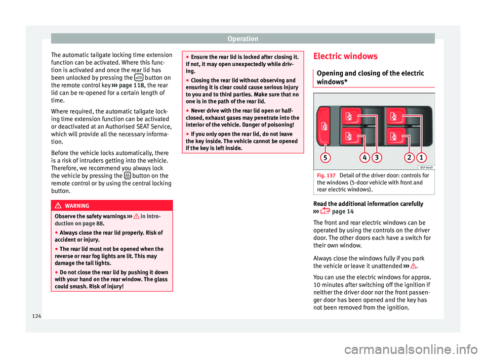
Detail of the driver door: controls for
the w indo
w
s (5-door vehicle with front and
rear electric windows). Read the additional information carefully
› ›
›
page 14
The front and rear electric windows can be
operated by using the controls on the driver
door. The other doors each have a switch for
their own window.
Always close the windows fully if you park
the vehicle or leave it unattended ››› .
Y ou c
an u
se the electric windows for approx.
10 minutes after switching off the ignition if
neither the driver door nor the front passen-
ger door has been opened and the key has
not been removed from the ignition.
124
Page 137 of 308
Lights and visibility
Dynamic headlight range control
The c ontr
o
l is not mounted in vehicles with
dynamic headlight range control. The head-
light range is automatically adjusted accord-
ing to the vehicle load status when they are
switched on.
Instrument panel lighting
With the ignition on and without light activa-
tion, the instrument panel lighting remains
activated in daytime light conditions. The
lighting is reduced as the exterior light di-
minishes. In some cases, e.g. when driving
through a tunnel without the function
active, the instrument panel lighting may
even switch off. The objective of this function
is to provide the driver with a visual indica-
tion that he or she should activate the dip-
ped beam. WARNING
Heavy objects in the vehicle may mean that
the hea dlight
s dazzle and distract other driv-
ers. This could result in a serious accident.
● Adjust the light beam to the vehicle load
stat
us so that it does not blind other drivers. Interior and reading lights
1)
›› ›
table on page 2
Read the additional information carefully
››› page 26
Glove compartment and luggage compart-
ment lighting*
When opening and closing the glove com-
partment on the front passenger side and the
rear lid, the respective light will automatically
switch on and off.
Footwell lighting*
The lights in the footwell area below the dash
(driver and front passenger sides) will switch
on when the doors are opened and will de-
crease in intensity while driving. The intensity
of these lights can be adjusted using the ra-
dio menu (see Easy Connect > Adjust-
ing Lighting > Interior lighting
››› page 28).
Ambient light*
The ambient light in the door panel changes
colour (white or red) depending on the driv-
ing mode. The intensity of these lights can be adjusted using the radio menu (see Easy
Connect > Adjusting Lights > In-
terior lighting › ›
›
page 28). Note
The reading lights switch off when the vehi-
cl e i
s locked using a key or after several mi-
nutes if the key is removed from the ignition.
This prevents the battery from discharging. Visibility
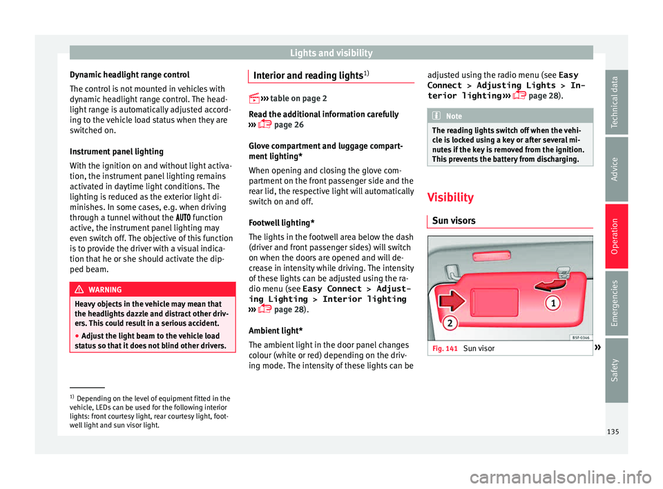
Su n
visors Fig. 141
Sun visor »1)
Depending on the level of equipment fitted in the
vehic l
e, LEDs can be used for the following interior
lights: front courtesy light, rear courtesy light, foot-
well light and sun visor light. 135
Technical data
Advice
Operation
Emergencies
Safety
Page 140 of 308
Operation
Rain sensor modified behaviour
P o
s
sible causes of faults and mistaken read-
ings on the sensitive surface ››› Fig. 144 of
the rain sensor include:
● Damaged blades: a film of water on the
damag
ed blades may lengthen the activation
time, reduce the washing intervals or result
in a fast and continuous wipe.
● Insects: insects on the sensor may trigger
the winds
creen wiper.
● Salt on roads: in winter, salt spread in the
roa
ds may cause an extra long wipe when the
windscreen is almost dry.
● Dirt: dry dust, wax, coating on glass (Lotus
effect) or trac
es of detergent (car wash) may
reduce the effectiveness of the rain sensor or
make it react more slowly, later or not at all.
● Cracked windscreen: the impact of a stone
wil
l trigger a single wipe cycle with the rain
sensor on. Next the rain sensor detects the
reduction in the sensitive surface area and
adapts accordingly. The behaviour of the sen-
sor will vary with the size of the damage
caused by the stone. WARNING
The rain sensor may not detect enough rain
to sw it
ch on the wipers.
● If necessary, switch on the wipers manually
when water on the w
indscreen obstructs visi-
bility. Note
● Cle
an the sensitive surface of the rain sen-
sor regularly and check the blades for dam-
age ››› Fig. 144 (arrow).
● To remove wax and coatings, we recom-
mend a window c
leaner containing alcohol. Rear vision mirror
Anti-dazz l
e rear vision mirrors Read the additional information carefully
› ›
›
page 17
Your vehicle is fitted with an interior rear vi-
sion mirror with a manual or automatic* con-
trol for anti-dazzle position.
Interior rear vision mirror with manual set-
ting for anti-dazzle position
– Position the small lever of the lower edge
of the mirror t
o face towards the rear. WARNING
In the event that an automatic anti-dazzle
re ar
vision mirror breaks, an electrolyte fluid
may leak. This could cause irritation to the
skin, eyes and respiratory organs. If you
come into contact with this liquid, it must be
rinsed with large quantities of water. If neces-
sary, get medial help. CAUTION
In the event that an automatic anti-dazzle
re ar
vision mirror breaks, an electrolyte fluid
may leak. This liquid attacks plastic surfaces.
Clean it with a wet sponge as soon as possi-
ble. Note
● If the light inc
ident in the interior rear vi-
sion mirror is obstructed (e.g. with the sun
blind*, the anti-dazzle rear vision mirror with
automatic setting will not operate perfectly.
● When the interior lights are on or reverse
gear en
gaged, the rear vision mirrors do not
darken with automatic adjustment for anti-
dazzle position. 138
Page 165 of 308
Air conditioning
Air recirculation mode Basic pointsAir recirculation:
Manual recirculation
Air recirculation mode prevents the ambient
air from ent
erin
g the interior.
When the outside temperature is very high,
selecting manual air recirculation mode for a
short period refreshes the vehicle interior
more quickly.
For safety reasons, air recirculation mode is
switched off when the button is press-
ed or the air distributor turned to .
Switching the manual air recirculation mode
on and off
To switch system on: press the button un-
til the warning lamp lights up.
To switch system off: press the button un-
til the warning lamp goes off.
Functioning mode of automatic air recircula-
tion (air conditioning menu)
With the automatic air recirculation mode ac-
tivated, the entry of fresh air into the cabin
interior is enabled. If the system detects a
high concentration of hazardous substances
in the ambient air, air recirculation mode is
switched on automatically. When the level of impurities drops to within a normal range, re-
cir
c
ulation mode is switched off.
The system is unable to detect unpleasant
smells.
The air recirculation will not connect auto-
matically in versions without humidity sensor
and in the following external conditions:
● The outside temperature is lower than +3°C
(+38°F).
● The cooling system is switched off and the
outside temper
ature is below +10°C (+50°F).
● The cooling system is switched off, the out-
side temper
ature is below +15°C (+59°F) and
the windscreen wipers are switched on.
Activation/deactivation of automatic air recir-
culation is done in the air conditioner menu,
under Configuration. WARNING
Observe the safety warnings ›››
in Intro-
duction on pag e 160
.
● If the cooling system is switched off and air
recir
culation mode switched on, the windows
can mist over very quickly, considerably limit-
ing visibility.
● Switch air recirculation mode off when it is
not requir
ed. CAUTION
Do not smoke when air recirculation is
swit c
hed on in vehicles with an air condition-
er. The smoke taken in could lie on the cool-
ing system vaporiser and on the activated
charcoal cartridge of the dust and pollen fil-
ter, leading to a permanently unpleasant
smell. Note
Climatronic: air recirculation mode is activa-
ted t o pr
event exhaust gas or unpleasant
odours from entering the vehicle interior
when it is in reverse and while the automatic
windscreen wiper is working. 163
Technical data
Advice
Operation
Emergencies
Safety
Page 228 of 308

Operation
Hitching and connecting the trailer Fig. 230
Schematic diagram: assignment of
the pins of the trailer's electrical socket.
Key of the Schematic diagram ››› Fig. 230:
PinMeaning
1Left turn signal
2Rear fog light
3Earth, pins 1, 2, 4 to 8
4Right turn signal
5Rear light, right
6Brake lights
7Rear light, left
8Reverse lights
9Permanent live
10Cable without positive charge
11Earth, pin 10
Key of the Schematic diagram ››› Fig. 230:
PinMeaning
12Unassigned
13Earth, pin 9 Electrical socket for trailer
The v
ehic
le is fitted with a 13-pole power
socket for the electrical connection between
the trailer and the vehicle. If the system de-
tects that a trailer has been connected elec-
trically, the electrical equipment on the trailer
will receive voltage through this connection.
Pin 9 has a permanent live. This powers, for
example, the trailer's interior lighting. Pin 10
is only powered when the engine is running.
The charge wire (pin 10) charges, for exam-
ple, a caravan battery.
Pin 9 and 10 should not be connected to
each other to avoid discharging or damaging
the vehicle's battery.
The earth wires, pin 3, pin 11 and pin 13,
should never be connected to each other to
avoid overloading the electrical system.
If the trailer has a 7-contact connector , you
will need to use an adapter cable. In this case
the function corresponding to pin 10 will not
be available. Trailer maximum electricity consumption
Brake lights (total)84 Watts
Turn signal, on each side42 Watts
Side lights (total)100 Watts
Rear lights (total)42 Watts
Rear fog light42 Watts
Never exceed the values indicated!
Note
● If the r e
ar lights of the trailer are not cor-
rectly connected, the vehicle electronics may
be damaged.
● If the trailer absorbs excessive electric cur-
rent, the v
ehicle electronics may be dam-
aged.
● Never connect the trailer's electric system
directly t
o the electrical connections of the
tail lights or any other power sources. Only
use the connections intended for providing
electric current to the trailer. Ball coupling of towing bracket de-
v
ic
e* The ball coupling is provided with instruc-
tion
s
on fittin
g and removing the ball cou-
pling of the towing bracket.
226
Page 255 of 308
Checking and refilling levels
CAUTION
● Do not mi x
cleaning products recommen-
ded by SEAT with other products. This could
lead to flocculation and may block the wind-
screen washer jets.
● When topping up service fluids, make abso-
lutely c
ertain that you fill the fluids into the
correct reservoirs. Using the wrong fluids
could cause serious malfunctions and engine
damage!
● Not having windscreen wiper fluid reduces
vis
ibility through the windscreen, and leads
to loss of visibility in headlights in models
with headlight washer. Battery
Gener a
l
informationRead the additional information carefully
› ›
›
page 53.
The battery is located in the engine compart-
ment and is almost maintenance-free. It is
checked as part of the Inspection Service.
Nevertheless, check the terminals are clean
and have the correct tightening torque, espe-
cially in summer and winter.
Disconnecting the battery
The battery should only be disconnected in
exceptional cases. When the battery is dis- connected, some of the vehicle's functions
are “los
t” (››› table on page 253). These
functions will require resetting after the bat-
tery is reconnected.
Deactivate the anti-theft alarm* before you
disconnect the battery Otherwise the alarm
will be triggered.
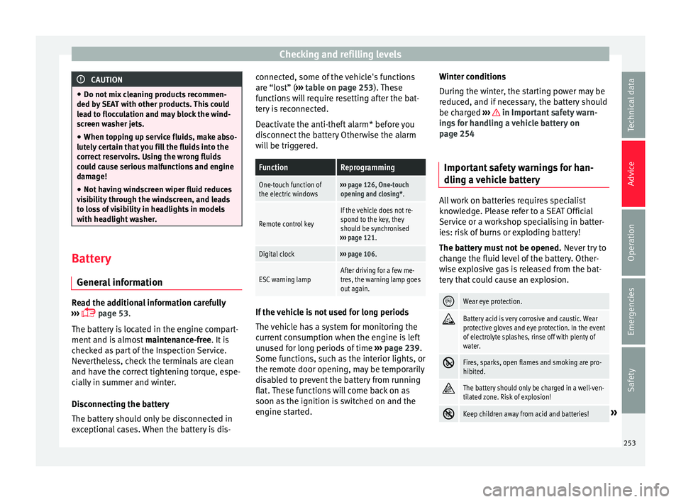
FunctionReprogramming
One-touch function of
the electric windows››› page 126, One-touch
opening and closing*.
Remote control key
If the vehicle does not re-
spond to the key, they
should be synchronised
››› page 121.
Digital clock››› page 106.
ESC warning lampAfter driving for a few me-
tres, the warning lamp goes
out again. If the vehicle is not used for long periods
The
v
ehic
le has a system for monitoring the
current consumption when the engine is left
unused for long periods of time ››› page 239.
Some functions, such as the interior lights, or
the remote door opening, may be temporarily
disabled to prevent the battery from running
flat. These functions will come back on as
soon as the ignition is switched on and the
engine started. Winter conditions
During the w
inter, the starting power may be
reduced, and if necessary, the battery should
be charged ››› in Important safety warn-
in g
s
for handling a vehicle battery on
page 254
Important safety warnings for han-
dling a v
ehicle battery All work on batteries requires specialist
kno
wl
edg
e. Please refer to a SEAT Official
Service or a workshop specialising in batter-
ies: risk of burns or exploding battery!
The battery must not be opened. Never try to
change the fluid level of the battery. Other-
wise explosive gas is released from the bat-
tery that could cause an explosion.
Wear eye protection.
Battery acid is very corrosive and caustic. Wear
protective gloves and eye protection. In the event
of electrolyte splashes, rinse off with plenty of
water.
Fires, sparks, open flames and smoking are pro-
hibited.
The battery should only be charged in a well-ven-
tilated zone. Risk of explosion!
Keep children away from acid and batteries!»
253
Technical data
Advice
Operation
Emergencies
Safety