2015 Seat Leon 5D bonnet
[x] Cancel search: bonnetPage 15 of 308

The essentials
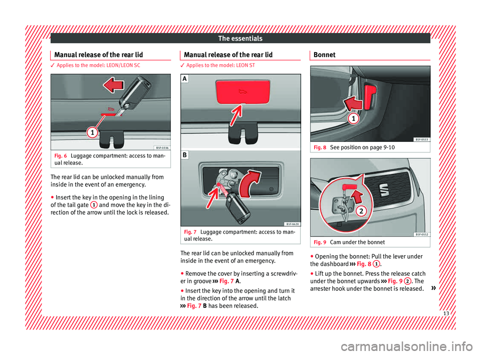
Manual release of the rear lid 3 Applies to the model: LEON/LEON SC
Fig. 6
Luggage compartment: access to man-
ual r
el
ease. The rear lid can be unlocked manually from
in
s
ide in the ev
ent of an emergency.
● Insert the key in the opening in the lining
of the tai
l gate 1 and move the key in the di-
r ection of
the arr
ow until the lock is released. Manual release of the rear lid 3 Applies to the model: LEON ST
Fig. 7
Luggage compartment: access to man-
ual r
el
ease. The rear lid can be unlocked manually from
in
s
ide in the ev
ent of an emergency.
● Remove the cover by inserting a screwdriv-
er in groov
e ››› Fig. 7 A.
● Insert the key into the opening and turn it
in the direction of the arr
ow until the latch
››› Fig. 7 B has been released. Bonnet
Fig. 8
See position on page 9-10 Fig. 9
Cam under the bonnet ●
Opening the bonnet: Pull the lever under
the d a
shbo
ard ›››
Fig. 8 1 .
● Lift up the bonnet. Press the release catch
u nder the bonnet
up
wards ›››
Fig. 9 2 . The
arr es
ter hook under the bonnet is released. » 13
Page 16 of 308

The essentials
● The bonnet c
an be opened. R
elease the
bonnet stay and secure it in the fixture de-
signed for this in the bonnet.
››› in Work in the engine compartment
on page 246
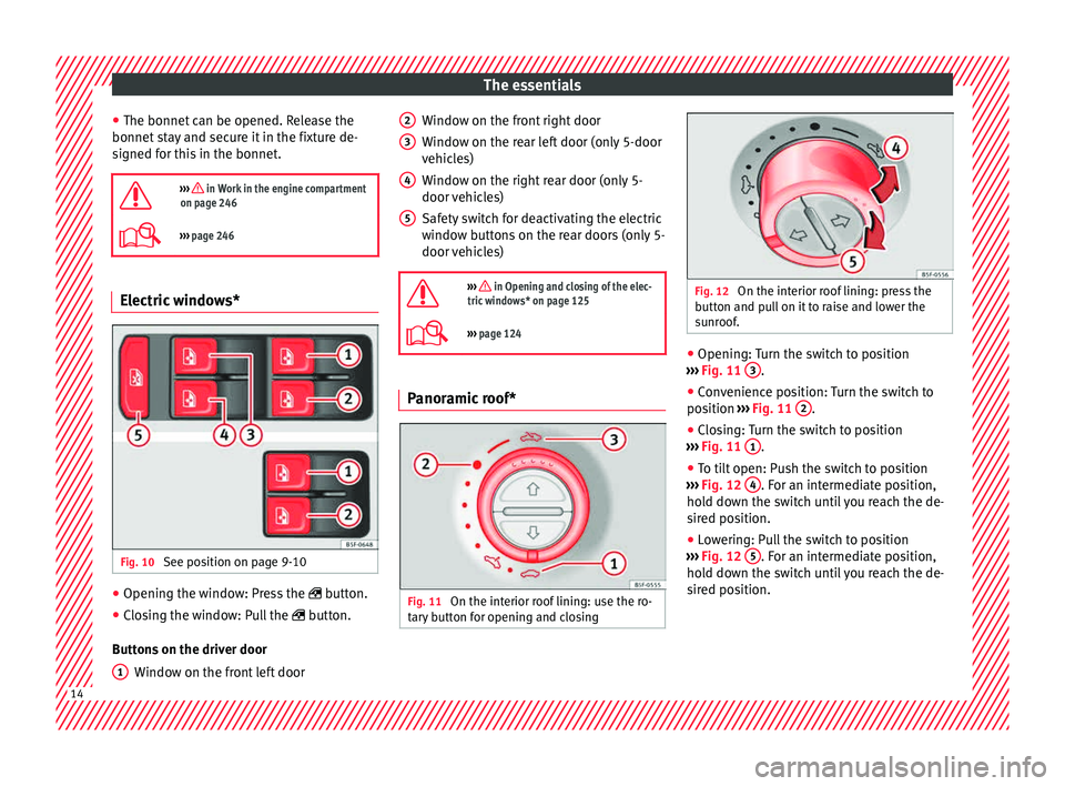
››› page 246 Electric windows*
Fig. 10
See position on page 9-10 ●
Opening the window: Press the butt
on.
● C
losing the window: Pull the button.
B
uttons on the driver door Window on the front left door
1 Window on the front right door
W
indo
w on the r
ear left door (only 5-door
vehicles)
Window on the right rear door (only 5-
door vehicles)
Safety switch for deactivating the electric
window buttons on the rear doors (only 5-
door vehicles)
››› in Opening and closing of the elec-
tric windows* on page 125
››› page 124 Panoramic roof*
Fig. 11
On the interior roof lining: use the ro-
t ar
y
button for opening and closing 2
3
4
5
Fig. 12
On the interior roof lining: press the
b utt
on and p
ull on it to raise and lower the
sunroof. ●
Opening: Turn the switch to position
› ›
›
Fig. 11 3 .
● Convenience position: Turn the switch to
po s
ition ›
›› Fig. 11 2 .
● Closing: Turn the switch to position
› ›
›
Fig. 11 1 .
● To tilt open: Push the switch to position
› ›
›
Fig. 12 4 . For an intermediate position,
ho l
d do
wn the switch until you reach the de-
sired position.
● Lowering: Pull the switch to position
›››
Fig. 12 5 . For an intermediate position,
ho l
d do
wn the switch until you reach the de-
sired position. 14
Page 36 of 308

The essentials
Bonnet, rear lid and doors open Fig. 47
A: bonnet open; B: rear lid open; C:
fr ont
l
eft door open; D: rear right door open
(5-door vehicles only). When the ignition is switched on or when
driv
in
g, the bonnet, r
ear lid or doors that are
open will be indicated on the instrument pan-
el display, and, as applicable, this will be in-
dicated audibly. The display may vary accord-
ing to the type of instrument panel fitted.
Illustra- tionKey to ››› Fig. 47
A Do not continue driving!
The bonnet is open or is not properly
closed ››› page 246.
B Do not continue driving!
The rear lid is open or is not properly
closed ››› page 123.
C, D Do not continue driving!
A vehicle door is open or is not properly
closed ››› page 116. Warning and information messages
The system runs a check on certain compo-
nents
and f
u
nctions when the ignition is
switched on and while the vehicle is moving.
Faults in the operation are displayed on the
screen using red and yellow symbols and
messages on the instrument panel display
( ›››
page 108) and, in some cases, with
audible warnings. The display may vary ac-
cording to the type of instrument panel fitted.
Priority 1 warning (red symbols)
Symbol flashing or lit; partly combined with audible
warnings.
Stop the vehicle! It is dangerous ››› in Warning
and indication lamps on page 109 !
Check the function that is faulty and repair it. If necessa-
ry, request assistance from specialised personnel.
Priority 2 warning (yellow symbols)
Symbol flashing or lit; partly combined with audible
warnings.
A faulty function, or fluids which are below the correct
levels may cause damage to the vehicle! ›››
in Warn-
ing and indication lamps on page 109
Check the faulty function as soon as possible. If neces-
sary, request assistance from specialised personnel.
Informative text
Information relating to different vehicle processes. Submenu Assist systems
Assist
systems
menuFunction
ACCDisplay of Adaptive Cruise Control
(ACC) ››› page 187.
Front As-
sistSwitching the monitoring system on
and off ››› page 197.
Lane As-
sist *Switching the Lane Assist system on or
off ››› page 203.
Detection
of traffic
signsDisplay of traffic signs ››› page 208:
Tiredness
detection *Switching the tiredness detection on
or off (pause recommendation)
››› page 210. 34
Page 44 of 308

The essentials
Front brake pads worn.
›››
page
178
it lights up:
Fault in the ESC, or dis-
connection caused by the system.
flashes: ESC or ASR activated.
ASR manually deactivated.
ESC in Sport mode or OFF
ABS faulty or does not work.
Rear fog light switched on.›››
page
128
lights up or flashes:
fault in the
emission control system.–
it lights up:
pre-ignition of diesel
engine.
››› page
109
flashes: fault in the diesel engine
management.
fault in the petrol engine manage-
ment.›››
page
109
lights up or flashes:
fault in the
steering system.››› page
238
Tyre pressure too low, or fault in
the tyre pressure monitoring sys-
tem.›››
page
259
Fuel tank almost empty.›››
page
104
Fault in airbag system and seat
belt tensioners.›››
page
77
Lane Assist is switched on, but not
active.›››
page
202 Other warning lamps
Left or right turn signal.›››
page
128
Hazard warning lights on.››› page
133
Trailer turn signals›››
page
220
it lights up:
Press the foot brake!
flashes: the selector lever locking
button has not engaged.››› page
167
it lights up:
cruise control activated
or speed limiter switched on and
active.
››› page
185
flashes: the speed set by the
speed limiter has been exceeded.
green warning lamp: Lane Assist is
switched on and active.›››
page
202
Main beam on or flasher on.›››
page
128 On the instrument panel display
Fig. 51
See position on page 9-10
Do not continue driving!
With the corresponding indica-
tion: door(s), rear lid or bonnet
open or not properly closed.››› page
116
››› page
123
››› page
246
Ignition: Do not carry on driv-
ing! Engine coolant level too low,
coolant temperature too high
››› page
250
Flashing: Fault in the engine
coolant system. 42
Page 66 of 308

The essentials
Make sure the battery clamps have sufficient
met al-t
o-met
al contact with the battery termi-
nals.
If the engine fails to start after about 10 sec-
onds, switch off the starter and try again after
about 1 minute. WARNING
● Ple a
se note the safety warnings referring to
working in the engine compartment
››› page 246.
● The battery providing assistance must have
the same v
oltage as the flat battery (12V) and
approximately the same capacity (see imprint
on battery). Failure to comply could result in
an explosion.
● Never use jump leads when one of the bat-
teries
is frozen. Danger of explosion! Even af-
ter the battery has thawed, battery acid could
leak and cause chemical burns. If a battery
freezes, it should be replaced.
● Keep sparks, flames and lighted cigarettes
awa
y from batteries, danger of explosion.
Failure to comply could result in an explo-
sion.
● Observe the instructions provided by the
manufact
urer of the jump leads.
● Do not connect the negative cable from the
other vehic
le directly to the negative terminal
of the flat battery. The gas emitted from the
battery could be ignited by sparks. Danger of
explosion. ●
Do not att ac
h the negative cable from the
other vehicle to parts of the fuel system or to
the brake line.
● The non-insulated parts of the battery
clamp
s must not be allowed to touch. The
jump lead attached to the positive battery
terminal must not touch metal parts of the ve-
hicle, this can cause a short circuit.
● Position the leads in such a way that they
cannot c
ome into contact with any moving
parts in the engine compartment.
● Do not lean on the batteries. This could re-
sult
in chemical burns. Note
The vehicles must not touch each other, oth-
erw i
se electricity could flow as soon as the
positive terminals are connected. Changing the wiper blades
W ind
s
creen wipers service position Fig. 80
Wipers in service position The wiper arms can be raised when the wip-
er
s
ar
e in service position ››› Fig. 80.
● Close the bonnet ›››
page 246.
● Switch the ignition on and off.
● Press the windscreen wiper lever down-
ward
s briefly 4
› ›
› page 27.
Before driving, always lower the wiper arms.
Using the windscreen wiper lever, the wind-
screen wiper arms return to their initial posi-
tion.
››› page 88 64
Page 91 of 308

Self-help
they should be changed if they are damaged,
or c l
e
aned if they are dirty ››› .
Dam ag
ed w
iper blades should be replaced
immediately. These are available from quali-
fied workshops. WARNING
Worn or dirty wiper blades reduce visibility
and incr e
ase the risk of accident and serious
injury.
● Always replace damaged or worn blades or
bla
des which do not clean the windscreen
correctly. CAUTION
● Damag ed or dir
ty windscreen wipers could
scratch the glass.
● If products containing solvents, rough
spong
es or sharp objects are used to clean
the blades, the graphite layer will be dam-
aged.
● Never use fuel, nail varnish remover, paint
thinner or simil
ar products to clean the win-
dows.
● In icy conditions, always check that the
wiper bl
ades are not frozen to the glass be-
fore using the wipers. In cold weather, it may
help to leave the vehicle parked with the wip-
ers in service position ›››
page 64. CAUTION
● To pr ev
ent damage to the bonnet and the
wiper arms, only leave them in the service
position.
● Before driving, always lower the wiper
arms. Towing and tow-starting the ve-
hicl
e
Gener
al information Read the additional information carefully
› ›
›
page 61. WARNING
If the vehicle has no electrical power, the
brak e light
s, turn signals and all other lights
will no longer function. Do not have the vehi-
cle towed away. Failure to follow this instruc-
tion could result in an accident. WARNING
The risk of accidents is high when tow-start-
ing, f or e
xample, the towed vehicle can easily
be driven into the towing vehicle. CAUTION
If there is no oil in the gearbox or no lubricant
in the autom atic
transmission the car may only be towed with the driven wheels lifted
cl
e
ar of the road, or transported on a special
car transporter or trailer. CAUTION
Do not tow a vehicle for more than 50 m in at-
t empt t
o start it. There is risk of damage to
the catalytic converter. Note
● Ple a
se observe related legal requirements.
● Switch on the hazard warning lights of both
vehicl
es. However, observe any regulations
to the contrary.
● The tow rope must not be twisted. Other-
wise the fr
ont tow line anchorage could be
pulled off the vehicle. 89
Technical data
Advice
Operation
Emergencies
Safety
Page 94 of 308

Emergencies
●
Never u se a f
use with a higher value. Only
replace fuses with a fuse of the same amper-
age (same colour and markings) and size.
● Never repair a fuse.
● Never replace a fuse by a metal strip, staple
or simil
ar. CAUTION
● To pr ev
ent damage to the vehicle's electric
system, before replacing a fuse always turn
off the ignition, the lights and all electrical
elements and remove the key from the igni-
tion.
● If you replace a fuse with higher-rating
fuse,
you could cause damage to another part
of the electrical system.
● Protect the fuse boxes when open to pre-
vent the entr
y of dust or humidity as they can
damage the electrical system. Note
● One component m
ay have more than one
fuse.
● Several components may run on a single
fuse. Vehicle fuses
Fig. 101
On the driver-side dash panel: fuse
bo x
c
over Fig. 102
In the engine compartment: fuse box
c o
v
er Read the additional information carefully
› ›
›
page 55
Only replace fuses with a fuse of the same
amperage (same colour and markings) and
size. Opening and closing the fuse box situated
below the da
sh panel
● Opening: fold the cover down ››
› Fig. 101.
● Closing: push back the cover it in until it
clic
ks into place.
To open the engine compartment fuse box
● Open the bonnet ›››
page 246.
● Press the locking tabs to release the fuse
box c
over ››› Fig. 102.
● Then lift the cover out.
● To fit the cover, place it on the fuse box.
Pu
sh the locking tabs down until they click
audibly into place.
Fuses in the vehicle interior
No.Consumers/Amps
4Taxis3
5Gateway5
6Automatic gearbox lever5
7Air conditioning and heating control
panel, heating the back window.10
8Diagnosis, handbrake switch, light
switch, reverse light, interior lighting10
9Steering column5
10Radio display5
12Radio20 92
Page 97 of 308

Fuses and bulbs
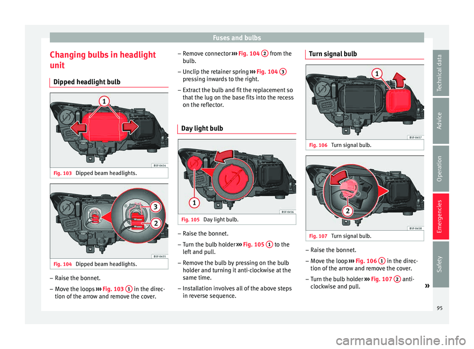
Changing bulbs in headlight
u nit
Dip ped he
adlight bulbFig. 103
Dipped beam headlights. Fig. 104
Dipped beam headlights. –
Raise the bonnet.
– Move the loops ››
›
Fig. 103 1 in the direc-
tion of the arr
o
w and remove the cover. –
Remov
e connector ››› Fig. 104 2 from the
b u
l
b.
– Unclip the retainer spring ›››
Fig. 104 3 pressing inwards to the right.
– Extract the bulb and fit the replacement so
th at
the lug on the b
ase fits into the recess
on the reflector.
Day light bulb Fig. 105
Day light bulb. –
Raise the bonnet.
– Turn the bulb holder ››
›
Fig. 105 1 to the
l ef
t
and pull.
– Remove the bulb by pressing on the bulb
holder and t
urning it anti-clockwise at the
same time.
– Installation involves all of the above steps
in rever
se sequence. Turn signal bulb
Fig. 106
Turn signal bulb. Fig. 107
Turn signal bulb. –
Raise the bonnet.
– Move the loop ››
›
Fig. 106 1 in the direc-
tion of the arr
o
w and remove the cover.
– Turn the bulb holder ›››
Fig. 107 2 anti-
c loc
k
wise and pull. »
95
Technical data
Advice
Operation
Emergencies
Safety