2015 Seat Altea XL turn signal
[x] Cancel search: turn signalPage 80 of 236
Operation
panel. The control lamp
flashes when the
t urn s
ignals are operated, provided a trailer is
correctly attached and connected to the vehi-
cle. If a turn signal bulb is defective, the con-
trol lamp flashes at double speed. If the trail-
er turn signal bulbs are defective, the control
lamp does not light up. Change the bulb.
● The main beam headlights can only be
sw
itched on if the dipped beam headlights
are already on. The warning lamp then
comes on in the instrument panel.
● The headlight flasher come
s on for as long
as you pull the lever – even if no other lights
are switched on. The warning lamp then
comes on in the instrument panel.
● When the parking lights are switched on,
the he
adlight and the tail light on the corre-
sponding side of the vehicle light up. The
parking lights will only work if the key is re-
moved from the ignition. If said light is on, an
audible warning will be emitted while the
driver door is open.
● If the turn signal lever is left on after the
key has been taken out of the ignition lock,
an acoustic signal sounds when the driver
door is opened. This is intended as a remind-
er to switch off the turn signal, unless you
wish to leave the parking light on. Daytime driving lights*
Daytime running lights are signalling devices
for improving road safety. The lights are built into the headlights and come on each time
the ignition is turned on if the light switch is
in position
0 or
. It is automatically
sw
itched off when the side lights are turned
on.
Automatic control of the dipped beam in
combination with the daytime running lights
If the dipped beam control and the daytime
running lights
are activated at the same
time, the dipped beams and the instrument
panel lighting will automatically come on as
required (e.g. when entering a tunnel) and
the daytime running lights will switch off.
When the automatic dipped beam control
switches off the dipped beams (e.g. when
coming out of a tunnel), the daytime running
lights come back on. WARNING
The side lights or daytime driving lights are
not bright enough to illuminate the road
ahead and to ensure that other road users are
able to see you.
● Always use your dipped beam head lights if
it is raining or if visibility is poor.
● The rear lights do not come on with the
daytime driving light. A vehicle which does
not have the rear lights on may not be visible
to other drivers in the darkness, if it is rain-
ing or in conditions of poor visibility. Note
Please observe any relevant legal require-
ments which may apply in your country. Nordic country solution
3 Only available in certain countries or as an
option
al
extra
The so-called “Nordic country solution” is an
alternative solution to daytime running lights
in vehicles without this function. It consists
of simultaneously connecting the dimmed
dipped beams, the sidelights and the licence
plate lights.
The aforementioned lights are switched on
each time the ignition is turned on if the light
switch is in position 0 or . Depending
upon the model, the control lamp on the
light control switch or the instrument panel
lighting will indicate that the lights are on.
Activation of the Nordic country solution
● Remove the key from the ignition, move the
turn signal lever upward (right turn signal),
press it back to flash position and hold it
there.
● Insert the key and switch on the ignition,
holding it in this position for 3 seconds.
Then, switch off the ignition. The Nordic
country solution is now activated and the cor-
responding lights can come on.
78
Page 81 of 236

Lights and visibility
Deactivation of the Nordic country solution
● Remove the key from the ignition, press the
turn signal lever down (left turn signal), press
it back to flash position and hold it here.
● Insert the key and switch on the ignition,
holding it in this position for 3 seconds.
Then, switch off the ignition. The Nordic
country solution is now deactivated and the
corresponding lights will not come on.
Coming Home/Leaving Home
function* The Coming Home function is controlled man-
ually. The Leaving Home function is control-
led with a photosensor.
If the Coming Home or Leaving Home func-
tion is connected, the front side and dipped
lights, the tail lights and the number plate
light will light up to provide assistance.
Coming home function
The Coming Home function is activated by
switching off the ignition and briefly flashing
the lights. When the driver door is opened,
the Coming Home lighting comes on. If the
driver door is already open when the lights
are flashed briefly, the Coming Home lighting
comes on
immediately .
When the l a
st door of the vehicle or the rear
lid is closed, the Coming Home function starts and the switching off the headlights is
delayed.
The Coming Home lighting switches off in the
following cases:
● On completion of the time period establish-
ed for the delay in switching off the lights af-
ter all the vehicle doors and the rear lid have
been closed.
● If, 30 seconds after being connected, any
doors or the rear lid remain open.
● If the light switch is turned to position
.
● If the ignition is switched on.
Leaving home function
The Leaving Home function is activated when
the vehicle is unlocked if:
● the light control is in position and
● the photosensor detects “darkness”.
The Leaving Home lighting switches off in the
following cases:
● If the time period for the delay in switching
off the headlights has ended
● If the vehicle is locked again.
● If the light switch is turned to position .
● If the ignition is switched on. Note
The setting for the delay in switching off the
headlights in the Coming Home and Leaving
Home function can be changed or the func-
tion can be connected or disconnected in the
menu Lights and visibility › ›
› page 56.
● If the ignition key is removed while the
lights are on, the lights flash briefly and the
driver door opens, no audible warning is
heard, since with the Coming Home function
on, the lights are automatically switched off
after a period of time (except when the light
switch is in position or . Instrument and switch lighting /
Headlight range control
Fig. 61
Dash panel: Instrument panel and
control dimmers and headlight range control. » 79
Technical specifications
Advice
Operation
Safety
Page 83 of 236

Lights and visibility
correct use of lights in all situations. “Auto-
matic headlight control” is merely a system
to support the driver. Where necessary,
switch on the lights manually using the light
switch.
Fog lights with cornering function*
3 Applies to the model: ALTEA / ALTEA XL
When the t urn s
ignal is switched on to turn or
on very tight bends, the right or left fog light
automatically comes on to function as a cor-
nering light. The cornering light only oper-
at e
s if the dipped beam lights are on. WARNING
Read and observe the relevant warnings ››› in Adaptive headlights* (for driving round
bends) on page 80 Hazard warning lights
Fig. 63
Dash panel: switch for hazard warn-
ing lights. The hazard warning lights are used to draw
the attention of other road users to your vehi-
cle in emergencies.
If your vehicle breaks down:
1. Park your vehicle at a safe distance from
moving traffic.
2. Press the button to switch on the hazard warning lights ››› .
3. Switch the ignition off.
4. Apply the handbrake.
5. For a manual gearbox, engage 1st gear; for an automatic gearbox, move the gear
lever to P
.
6.
Use the warning triangle to draw the atten-
tion of other road users to your vehicle. 7. Always take the vehicle key with you when
you leave the vehicle.
Switch on the hazard warning lights to warn
other road users, for example:
● reaching the tail end of a traffic jam,
● there is an emergency
● your vehicle breaks down due to a techni-
cal fault,
● you are towing another vehicle or your vehi-
cle is being towed.
All turn signals flash simultaneously when
the hazard warning lights are switched on.
The two turn signal turn signal lamps
and the turn signal lamp in the switch will
flash at the same time. The hazard warning
lights also work when the ignition is switch-
ed off.
Emergency braking warning
If the vehicle brakes suddenly and continu-
ously at a speed of more than 80 km/h (50
mph), the brake light flashes several times
per second to warn the vehicles driving be-
hind. If you continue braking, the hazard
warning lights will come on automatically
when the vehicle comes to a standstill. They
switch off automatically when the vehicle
starts to move again. »
81
Technical specifications
Advice
Operation
Safety
Page 144 of 236
Operation
detected while driving forward. The optical
display changes to towing mode.
Fault messages If you hear a long beep for a few seconds and
the LED on the switch
* starts flashing
when
you switch on the parking aid, a system
fault has occurred. Contact a SEAT official
service or specialised workshop. Note
If the fault is not corrected before you switch
off the ignition, it will only be indicated by
the flashing LED on the switch the next
time y
ou switch on the parking aid. Cruise speed* (cruise control
system - CCS)
Description The CCS is able to maintain the set speed in
the range from approx. 30 km/h (19 mph) to
180 km/h (112 mph).
Once the speed setting has been saved, you
may take your foot off the accelerator. WARNING
It could be dangerous to use the cruise con-
trol system if it is not possible to drive at con-
stant speed.
● Do not use the cruise control system when
driving in dense traffic, on roads with lots of
bends or on roads with poor conditions (with
ice, slippery surfaces, loose grit or gravel), as
this could cause an accident.
● Always switch the cruise control system off
after using it in order to avoid involuntary
use.
● It is dangerous to use a set speed which is
too high for the current road, traffic or weath-
er conditions. Risk of accident. Note
The cruise control cannot maintain a constant
speed when descending downhill. It will in-
crease due to its own weight. Use the foot
brake to slow the vehicle. Switching the cruise control system
on and off
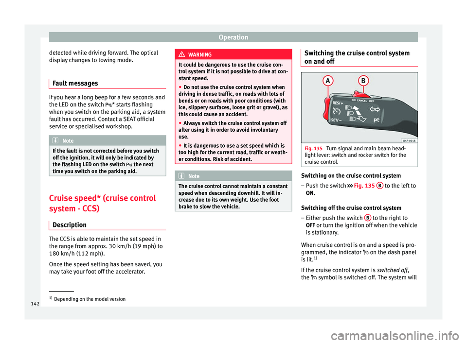
Fig. 135
Turn signal and main beam head-
light lever: switch and rocker switch for the
cruise control. Switching on the cruise control system
– Push the switch ››› Fig. 135 B to the left to
ON.
Switching off the cruise control system
– Either push the switch B to the right to
OFF or turn the ignition off when the vehicle
is stationary.
When cruise control is on and a speed is pro-
grammed, the indicator on the dash panel
is lit. 1)
If the cruise control system is switched off,
the symbo l
is switched off. The system will 1)
Depending on the model version
142
Page 145 of 236

Driver assistance systems
also be switched off fully when the 1st gear
i s
engaged.*
Setting speed* Fig. 136
Turn signal and main beam head-
light lever: switch and rocker switch for the
cruise control. –
Press the lower part SET/- of the rocker
switch ››› Fig. 136 A once briefly when you
have reached the speed you wish to set.
When you release the rocker switch, the cur-
rent speed is set and held constant.
Adjusting set speed* The speed can be altered without touching
the accelerator or the brake. Setting a higher speed
– Press the upper part RES/+ of the rocker
switch ››› Fig. 136 A to increase the speed.
The vehicle will continue to accelerate as
long as you keep the rocker switch pressed.
When you release the switch, the new
speed is stored.
Setting a lower speed – Press the lower part SET/– ››› Fig. 136 A of
the rocker switch to reduce the speed. The
vehicle will automatically reduce its speed
for as long as you keep the switch pressed.
When you release the switch, the new
speed is stored.
When you increase speed with the accelera-
tor and then release the pedal, the system
will automatically restore the set speed. This
will not be the case, however, if the vehicle
speed exceeds the stored speed by more
than 10 km/h (6 mph) for longer than 5 mi-
nutes. The speed will have to be stored
again.
Cruise control is switched off if you reduce
speed by depressing the brake pedal. You
can reactivate the control by pressing once
on the upper part of the rocker switch RES/+
››› Fig. 136 A .Switching off cruise control
temporarily*
Fig. 137
Turn signal and main beam head-
light lever: switch and rocker switch for the
cruise control. The cruise control system will be switched off
in the following situations:
● if the brake pedal is depressed,
● if the clutch pedal is depressed,
● if the vehicle is accelerated to over
180 km/h (112 mph),
● when the ESC or ASR is used.
● when the lever B is moved to the position
CANCEL without reaching the OFF position.
Once the CANCEL operation is complete,
when the lever is released it returns to its ini-
tial position.
To resume cruise control, release the brake or
clutch pedal or reduce the vehicle speed to
less than 180 km/h (112 mph) and press »
143
Technical specifications
Advice
Operation
Safety
Page 194 of 236
Advice
Driving style
Towing requires some experience, especially
when using a tow rope. Both drivers should
be familiar with the technique required for
towing. Inexperienced drivers should not at-
tempt to tow.
Do not pull too hard with the towing vehicle
and take care to avoid jerking the tow rope.
When towing on an unpaved road, there is al-
ways a risk of overloading and damaging the
anchorage points.
The ignition of the vehicle being towed must
be switched on to prevent the steering wheel
from locking and also to allow the use of the
turn signals, horn, windscreen wipers and
washers.
The brake servo only works when the engine
is running. When not running, you must ap-
ply considerably more pressure to the brake
pedal.
As the power assisted steering does not work
if the engine is not running, you will need
more strength to steer than you normally
would.
● The vehicle must not be towed faster than
50 km/h (31 mph).
Towing vehicles with an automatic gearbox
● Put the selector lever into position “N”.
● Do not drive faster than 50 km/h (31 mph). ●
Do not tow further than 50 km.
● If a breakdown vehicle is used, the vehicle
must be towed with the front wheels raised. Note
● Observe legal requirements when towing or
tow-starting.
● Switch on the hazard warning lights of both
vehicles. However, observe any regulations
to the contrary.
● For technical reasons, vehicles with an au-
tomatic gearbox must not be tow-started.
● If there is no lubricant in the gearbox as the
result of a fault, you must raise the driven
wheels while the vehicle is being towed.
● If the vehicle has to be towed more than
50 km, the front wheels should be raised dur-
ing towing, and towing should be carried out
by a qualified person.
● The steering wheel is locked when the vehi-
cle has no electrical power. The vehicle must
then be towed with the front wheels raised.
Towing should be carried out by a qualified
person.
● The towline anchorage should always be
kept in the vehicle. Please refer to the notes
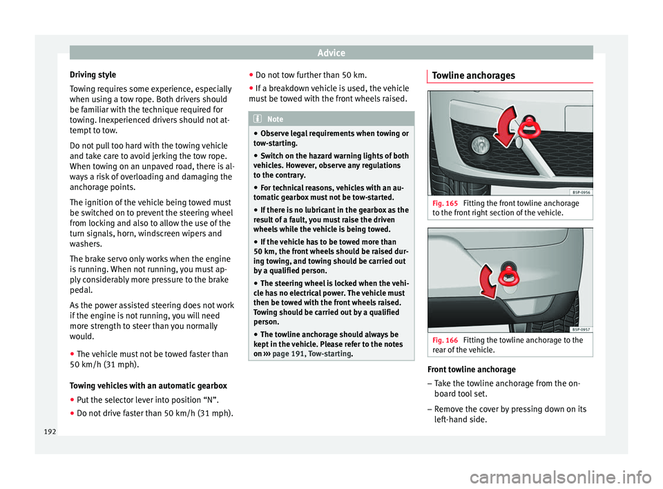
on ››› page 191, Tow-starting. Towline anchorages
Fig. 165
Fitting the front towline anchorage
to the front right section of the vehicle. Fig. 166
Fitting the towline anchorage to the
rear of the vehicle. Front towline anchorage
– Take the towline anchorage from the on-
board tool set.
– Remove the cover by pressing down on its
left-hand side.
192
Page 201 of 236

Fuses and bulbs
the following spare bulbs, which are essen-
tial for road safety, should be kept in the ve-
hicle.
Main headlights - H7
- H1
- W5W - PY21W
Xenon headlights 1)
/adaptive*
- D1S 2)
- P21W SLL
- W5W - PY21W
Front fog light - H3
Dipped beam
Main beam
Position
Turn signal
Dipped and full beam
Daylight
Position
Turn signals
Front fog light Upper tail light (ALTEA)
- P21W3)
- R10W
Lower tail light (ALTEA) - P21W- P21W
Fixed tail light (ALTEA XL / ALTEA FREETRACK) - P21W3)
- P21W
Mobile tail light (ALTEA XL / ALTEA
FREETRACK) - P21W- P21W
- W5W
Stop/Position
Turn signal
Fog light
Reverse light
Stop/Position
Turn signal
Fog light (driver side)
Reverse (passenger side)
Position Side turn signal
- W5W
Number plate light - C5W Note
● Depending on weather conditions (cold or
wet), the headlights, the fog lights, the tail
lights and the turn signals may be temporari-
ly misted. This has no influence on the useful
life of the lighting system. By switching on
the lights, the area through which the beam
of light is projected will quickly be demisted.
However, the edges may continue to be mis-
ted.
● Please check at regular intervals that all
lighting (especially the exterior lighting) on
your vehicle is functioning properly. This is » Side turn signal
Number plate light
1)
On this type of headlight, the bulb changes must
be made by the technical service, given that complex
elements must be removed from the vehicle and the
incorporated automatic control system must be re-
set.
2) The Xenon bulbs discharge 2.5 times the light flux
and have an average lifespan of 5 times more than
that of halogen bulbs, this means that, except due to
unusual circumstances, there is no need to change
the bulbs for the whole life of the vehicle.
3) Electronically controlled single filament bulb for
Stop/side bulbs. If the bulb blows it will not work in
either position or Stop. 199Technical specifications
Advice
Operation
Safety
Page 202 of 236
Advice
not only in the interest of your own safety,
but also that of all other road users.
● Due to difficulty of access to some of the
bulbs, any replacement work should be done
by a technical service. However, the following
is a description of how to change the lamps
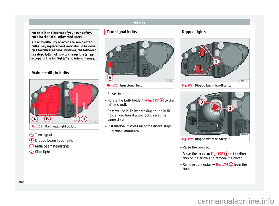
except for the fog lights* and interior lamps. Main headlight bulbs
Fig. 176
Main headlight bulbs. Turn signal
Dipped beam headlights
Main beam headlights
Side light
A B
C
D Turn signal bulbs
Fig. 177
Turn signal bulb. –
Raise the bonnet.
– Rotate the bulb holder ››› Fig. 177 A to the
left and pull.
– Remove the bulb by pressing on the bulb
holder and turn it anti-clockwise at the
same time.
– Installation involves all of the above steps
in reverse sequence. Dipped lights Fig. 178
Dipped beam headlights. Fig. 179
Dipped beam headlights. –
Raise the bonnet.
– Move the loops ››› Fig. 178 1 in the direc-
tion of the arrow and remove the cover.
– Remove connector ››› Fig. 179 2 from the
bulb.
200