Page 265 of 305

Emergencies
Changing the wiper blades Changing windscreen wiper blades Fig. 205
Changing the front wiper blades Fig. 206
Changing the rear wiper blade The windscreen wiper blades are supplied as
standard with a layer of graphite. This layer is
responsible for ensuring that the wipe is si-
lent. If the graphite layer is damaged, the noise of the water as it is wiped across the
windscreen will be louder.
Check the condition of the wiper blades regu-
larly.
If the wipers scrape across the glass
they shou
ld be changed if they are damaged,
or cleaned if they are dirty ››› .
Damaged wiper blades should be replaced
immediately. These are available from quali-
fied workshops.
Lifting and unfolding the wiper arms
The wiper arm may only be lifted at the point
wher e it
is fastened to the blade.
For windscreen wipers, please note: the wip-
er should be in service position before un-
folding it ››› page 81.
Cl
eaning windscreen wiper blades
● Lifting and unfolding the wiper arms.
● Use a soft cloth to remove dust and dirt
from the windscreen wiper blades.
● If the blades are very dirty, a sponge or
damp cloth may be used ››› .
Changing the windscreen wiper blades
● Lifting and unfolding the wiper arms.
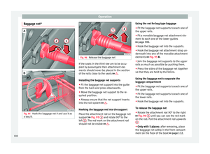
● Hold down the release button ››› Fig. 205
1 while gently pulling the blade in the direc-
tion of the arrow. ●
Fit a new wiper blade of the same length
and design on to the wiper arm and hook it
int o p
lace.
● Rest the wiper arms back onto the wind-
screen.
Changing the rear wiper blade
● Lift and unfold the wiper arm.
● Pull the wiper blade out of its mounting on
the wiper arm ››› Fig. 206 (arrow A ).
● Hold down the release button ››› Fig. 206
1 while gently pulling the blade in the direc-
tion of the arrow B . This may require some
strength.
● Insert a new blade of the same length and
type in the wiper arm in the opposite direc-
tion t o the arr
ow ››› Fig. 206 B and hook into
place. This feature is operational when the
knob is in position (arrow A ).
● Replace the wiper arm on the rear window. WARNING
Worn or dirty wiper blades reduce visibility
and increase the risk of accident and serious
injury.
● Always replace damaged or worn blades or
blades which do not clean the windscreen
correctly. » 263
Technical specifications
Advice
Operation
Safety
Page 266 of 305

Advice
CAUTION
● Damaged or dirty windscreen wipers could
scratch the glass.
● If products containing solvents, rough
sponges or sharp objects are used to clean
the blades, the graphite layer will be dam-
aged.
● Never use fuel, nail varnish remover, paint
thinner or similar products to clean the win-
dows. Fuses and bulbs
Fuses Introduction Due to the constant updating of vehicles,
fuse assignments based on equipment and
the use of the same fuse for various electrical
components, it is not possible to provide an
up-to-date summary of the fuse positions for
the electrical components at the time of
printing this manual. For detailed information
about the fuse positions, please consult a
technical service.
In general, a fuse can be assigned to various
electrical components. Likewise, an electrical
component can be protected by several
fuses.
Only replace fuses when the cause of the
problem has been solved. If a newly inserted
fuse blows after a short time, you must have
the electrical system checked by a special-
ised workshop as soon as possible.
WARNING
The high voltages in the electrical system can
give serious electrical shocks, causing burns
and even death!
● Never touch the electrical wiring of the igni-
tion system. ●
Take care not to cause short circuits in the
electrical system. WARNING
Using unsuitable fuses, repairing fuses or
bridging a current circuit without fuses can
cause a fire and serious injury.
● Never use a fuse with a higher value. Only
replace fuses with a fuse of the same amper-
age (same colour and markings) and size.
● Never repair a fuse.
● Never replace a fuse by a metal strip, staple
or similar. CAUTION
● To prevent damage to the vehicle's electric
system, before replacing a fuse always turn
off the ignition, the lights and all electrical
elements and remove the key from the igni-
tion.
● If you replace a fuse with higher-rating
fuse, you could cause damage to another part
of the electrical system.
● Protect the fuse boxes when open to pre-
vent the entry of dust or humidity as they can
damage the electrical system. Note
● One component may have more than one
fuse. 264
Page 267 of 305

Fuses and bulbs
●
Several components may run on a single
fuse. Vehicle fuses
Fig. 207
On the driver-side dash panel: fuse
box cover Fig. 208
In the engine compartment: fuse box
cover Only replace fuses with a fuse of the same
amperage (same colour and markings) and
size.
Identifying fuses by coloursColourAmp rating
Purple3
Light brown5
Brown7.5
Red10
Blue15
Yellow20
White or trans-
parent25
Green30
Orange40 To open the dash panel fuse box
●
To remove the cover, move the activation
lever in the lower part to the right ››› Fig. 207.
● For right-hand drive vehicles, move the lev-
er to the left.
To open the engine compartment fuse box
● Open the bonnet ››› page 214. ●
Move the attachment tabs forwards, in the
direction indicated by the arrow to release
the fuse box cover ››› Fig. 208 .
● Then lif t
the cover out.
● To
fit the cover, place it on the fuse box.
Push the attachment tabs back, in the oppo-
site direction indicated by the arrow until
they click audibly into place.
In is possible that there are more fuses be-
hind a cover in the lower left-hand side of the
luggage compartment. CAUTION
● Always carefully remove the fuse box cov-
ers and refit them correctly to avoid problems
with your vehicle.
● Protect the fuse boxes when open to avoid
the entry of dust or humidity. Dirt and humid-
ity inside fuse boxes can cause damage to
the electrical system. Note
In the vehicle, there are more fuses than
those indicated in this chapter. These should
only be changed by a specialised workshop. 265
Technical specifications
Advice
Operation
Safety
Page 268 of 305

Advice
Replacing a blown fuse Fig. 209
Image of a blown fuse Fig. 210
Removing or fitting a fuse Preparation
● Switch off the ignition, lights and all elec-
trical equipment.
● Open the corresponding fuse box
››› page 265 Identifying a blown fuse
A fuse is blown if its metal strip is ruptured
››› Fig. 209 .
P oint
a lamp at the fuse. This will make it
easier to see if the fuse is blown.
To replace a fuse
● If necessary, remove the plastic pincers
from the fuse box cover.
● For
small fuses, insert the pincers from
above ››› Fig. 210 A.
● For
larger fuses , insert the pincers from one
side of the fuse ››› Fig. 210 B.
● Remove the relevant fuse.
● Replace the blown fuse by one with an
identical amperage rating (same colour and
mark
ings) and identical size ››› .
● Replace the cover. CAUTION
If you replace a fuse with higher-rating fuse,
you could cause damage to another part of
the electrical system. Changing bulbs
Introduction Changing bulbs requires a certain amount of
manual skill. If you are unsure, SEAT recom-
mends that you consult a technical service or
request assistance from a specialist. In gen-
eral, a specialist is required if other vehicle
components must be removed or if the dis-
charge lamps must be replaced.
You should store spare light bulbs in the ve-
hicle for safety-relevant lights. Spare bulbs
may be obtained from the technical services.
In some countries, it is a legal requirement to
carry spare bulbs in the vehicle.
Driving with faults and blown bulbs on the
vehicle exterior lighting is against the law.
Additional bulb specifications
The specifications of some headlamp bulbs
and bulbs for the tail lamps fitted at the fac-
tory may be different to those of conventional
bulbs. Bulb information is displayed on the
bulb socket or on the bulb itself.
WARNING
If the road is not well-lit and the vehicle is
not clearly visible to other drivers, there is a
risk of accident. 266
Page 269 of 305

Fuses and bulbs
WARNING
Failure to replace bulbs correctly may cause
serious accidents.
● Before carrying out any work in the engine
compartment please read and observe the
warnings ››› page 214. In any vehicle, the en-
gine c omp
artment is a hazardous area and
could cause severe injury.
● Discharge lamps work with high-voltage
and can cause serious or fatal injury if han-
dled incorrectly.
● H7 and discharge lamps are highly pressur-
ised and could explode when being changed.
● Only replace the bulbs concerned when
they have cooled.
● Never replace bulbs alone if you are not fa-
miliar with the operations necessary. If you
are not sure about procedures then visit a
specialised workshop to carry out the neces-
sary work.
● Never touch the bulb glass directly. Finger-
prints will be evaporated by the heat of the
operating bulb thus “fogging” up the reflec-
tor.
● The headlamp frameworks in the engine
compartment and the tail lamps contain sharp elements. Always protect your hands
when changing bulbs.
CAUTION
● After changing a bulb, if the rubber covers
are not replaced correctly on the headlamp
framework, the electrical installation may be
damaged, especially if water is allowed to en-
ter.
● Remove the ignition key before working on
the electric system. Otherwise, a short circuit
could occur.
● Switch off the lights and the parking light
before changing a bulb.
● Take good care to avoid damaging any com-
ponents. Control lamp
It
lights upPossible causeSolution
A vehicle exterior
lighting bulb is not
working.Replace the faulty
bulb. Several warning and control lamps light up
for a few seconds when the ignition is switch-
ed on, signalling that the function is being
verified. They will switch off after a few sec-
onds.
Checking the bulbs of a trailer
For vehicles with the factory fitted towing
bracket, certain trailer lights are also control-
led if the power socket is correctly connected.
A fault on a trailer turn signal is indicated on
the instrument panel by the turn signal blink-
ing twice as fast (
or ) ››› page 74.
● General fault of all turn signals on one side.
● Fault in one tail light (on some models, al-
so the registration light).
● Fault in two brake lights. WARNING
Observe the safety warnings ››› in Control
and warning lamps on page 47. Note
A fault in the LED on the tail lights will not be
indicated. However, if the fault affects all the
LEDs then this will be indicated by the control
lamp . 267
Technical specifications
Advice
Operation
Safety
Page 270 of 305

Advice
To replace halogen headlight bulbs Fig. 211
In the engine compartment: left-
hand side headlight lining. A dipped beam
headlights, B daytime driving lights and
Cmain beam headlights and side lights Fig. 212
Left headlight. There is no need to remove the headlight to
replace bulbs.
Complete operations only in the sequence
given:
ABC
Turn signals (small lamp holder)Dipped beam
headlightsDaytime driving lightMain beam headlightsSide lights
1.Open the bonnet ››› page 214.
2. Remove the rubber cover on the rear of the headlight.
3.Rotate the lamp holder 1 to the left
all the way and pull it out backwards with the bulb.Rotate the lamp holder to the left all the wayand pull it out backwards with the bulb.Press the wire clip downwards and
pull the lamp holder 2 out with the
bulb.Pull the lamp holder 3 out back-
wards with the bulb.
4.Depending on the model, the bulb is removed directly from the lamp holder or it may need to be rotated and then removed.
5.Replace the faulty bulb by a new identical bulb. 268
Page 271 of 305

Fuses and bulbs
ABC
Turn signals (small lamp holder)Dipped beam
headlightsDaytime driving lightMain beam headlightsSide lights
6.Place the bulb holder in the headlight and rotate to the right all the way.Place the lamp holder in the head-
light and pull the wire clip upwards until it clicks into place.Place the lamp holder in the head-light and insert completely.
7. Insert the rubber cover. Note
The images show the left hand headlight
from behind. The structure of the right hand
side headlight is symmetric. To replace the xenon headlights bulb
Fig. 213
In the engine compartment: turn sig-
nal indicator cover. Fig. 214
Turn signal lamp holder 1 and turn-
ing light 2 There is no need to remove the headlight to
replace bulbs.
Complete operations only in the sequence
given:
Turn signals
1Turning lights 2
1.Open the bonnet
››› page 214.
2.Rotate the cover ››› Fig. 213 in the direction of the
arrow and remove it.
Turn signals 1Turning lights 2
3.
Rotate the lamp holder
1 ››› Fig. 214 to the
left all the way and pull
it out backwards with
the bulb.Press the wire clip
downwards and pull the
lamp holder 2
›››
Fig. 214 out with the
bulb.
4.Depending on the model, the bulb is removed di-
rectly from the lamp holder or it may need to be ro- tated and then removed.
5.Replace the faulty bulb by a new identical bulb.
6.
Place the bulb holder in
the headlight and ro-
tate to the right all the
way.Place the lamp holder
in the headlight and
pull the wire clip up-
wards until it clicks into
place.
7.Rotate the cover ››› Fig. 213 in the opposite direc-
tion to the arrow as far as it will go. Always seek the help of a specialist when
changing the Xenon dipped beam and main
beam headlamps
››› in Introduction on
page 267. »
269
Technical specifications
Advice
Operation
Safety
Page 272 of 305

Advice
Note
The illustrations show the left hand head-
light. The structure of the right hand side
headlight is symmetric. To replace the front bumper bulbs
Fig. 215
On the right-hand side of the front
bumper: removing the headlights. Fig. 216
Changing the bulbs in the head-
lights Complete operations only in the sequence
given:1.Pull the cover forwards, in the direction of the ar-
row
››› Fig. 215.
2.Unscrew the attachment screw ››› Fig. 215 1 us-
ing the screwdriver from the vehicle tool kit
››› page 244.
3.Tilt the headlight slightly forward and extract it
from its lateral attachments ››› Fig. 216 (small ar-
rows).
4.Release the connector ››› Fig. 216 1 and remove
it.
5.Rotate the bulb holder ››› Fig. 216 2 to the left all
the way, in the direction of the arrow, and pull it
out backwards with the bulb.
6.Replace the faulty bulb by a new identical bulb.
7.Place the bulb holder in the headlight and rotate
to the right all the way.
8.Insert the connector ››› Fig. 216 1 on the bulb
holder 2. The connector must audibly click into
place.
9.Place the headlight into its position ››› Fig. 216
(small arrows) and tilt it backwards.
10.Tighten the attachment screw ››› Fig. 215 1 us-
ing the screwdriver.
11.Replace the cover on the bumper ››› Fig. 215. 270