Page 202 of 268

5.6
TYRE INFLATION KIT (4/5)
Inflation kit D
Depending on the vehicle, in the event
of a puncture, use the kit located in the
boot or underneath the luggage com-
partment carpet.
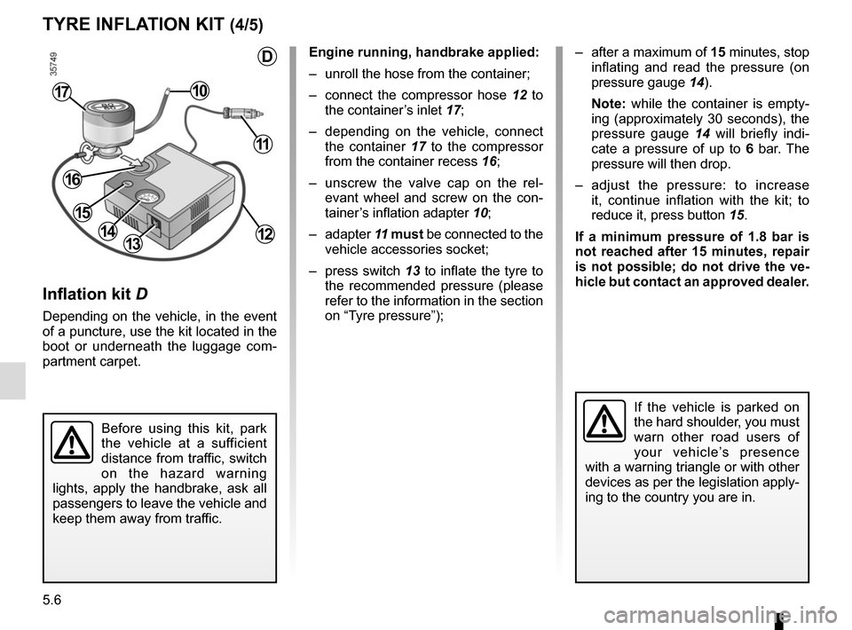
Engine running, handbrake applied:
– unroll the hose from the container;
– connect the compressor hose 12 to
the container’s inlet 17;
– depending on the vehicle, connect the container 17 to the compressor
from the container recess 16;
– unscrew the valve cap on the rel- evant wheel and screw on the con-
tainer’s inflation adapter 10;
– adapter 11 must be connected to the
vehicle accessories socket;
– press switch 13 to inflate the tyre to
the recommended pressure (please
refer to the information in the section
on “Tyre pressure”);
1314
10
Before using this kit, park
the vehicle at a sufficient
distance from traffic, switch
on the hazard warning
lights, apply the handbrake, ask all
passengers to leave the vehicle and
keep them away from traffic.
17
If the vehicle is parked on
the hard shoulder, you must
warn other road users of
your vehicle’s presence
with a warning triangle or with other
devices as per the legislation apply-
ing to the country you are in.
– after a maximum of 15 minutes, stop inflating and read the pressure (on
pressure gauge 14).
Note: while the container is empty-
ing (approximately 30 seconds), the
pressure gauge 14 will briefly indi-
cate a pressure of up to 6 bar. The
pressure will then drop.
– adjust the pressure: to increase it, continue inflation with the kit; to
reduce it, press button 15.
If a minimum pressure of 1.8 bar is
not reached after 15 minutes, repair
is not possible; do not drive the ve-
hicle but contact an approved dealer.
11
12
16
15
D
Page 206 of 268

5.10
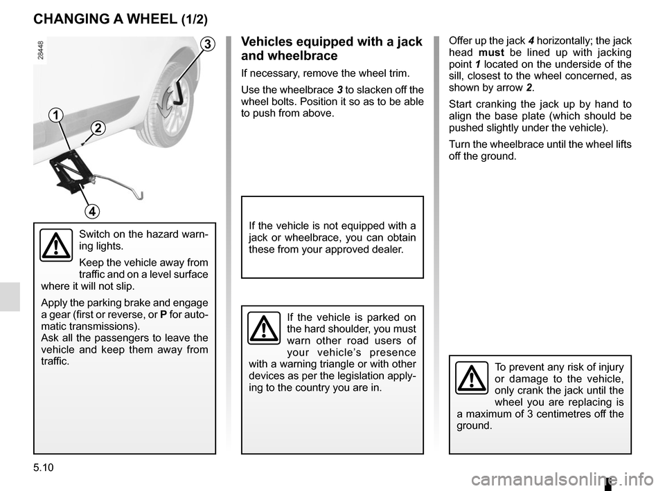
Offer up the jack 4 horizontally; the jack
head must be lined up with jacking
point 1 located on the underside of the
sill, closest to the wheel concerned, as
shown by arrow 2.
Start cranking the jack up by hand to
align the base plate (which should be
pushed slightly under the vehicle).
Turn the wheelbrace until the wheel lifts
off the ground.
Switch on the hazard warn-
ing lights.
Keep the vehicle away from
traffic and on a level surface
where it will not slip.
Apply the parking brake and engage
a gear (first or reverse, or P for auto-
matic transmissions).
Ask all the passengers to leave the
vehicle and keep them away from
traffic.
3
1
2
4
CHANGING A WHEEL (1/2)
To prevent any risk of injury
or damage to the vehicle,
only crank the jack until the
wheel you are replacing is
a maximum of 3 centimetres off the
ground.
If the vehicle is parked on
the hard shoulder, you must
warn other road users of
your vehicle’s presence
with a warning triangle or with other
devices as per the legislation apply-
ing to the country you are in.
Vehicles equipped with a jack
and wheelbrace
If necessary, remove the wheel trim.
Use the wheelbrace 3 to slacken off the
wheel bolts. Position it so as to be able
to push from above.
If the vehicle is not equipped with a
jack or wheelbrace, you can obtain
these from your approved dealer.
Page 211 of 268

5.15
Do not touch the bulb glass. Hold it
by its base.
When the bulb has been changed,
make sure you refit the cover correctly.
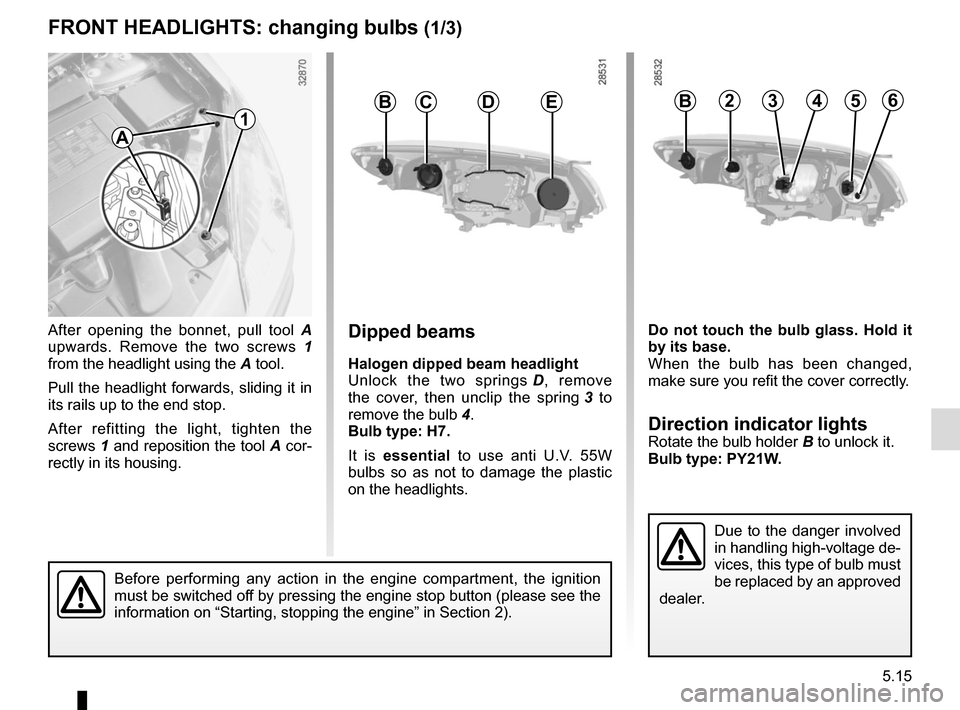
Direction indicator lightsRotate the bulb holder B to unlock it.
Bulb type: PY21W.
FRONT HEADLIGHTS: changing bulbs (1/3)
After opening the bonnet, pull tool A
upwards. Remove the two screws 1
from the headlight using the A tool.
Pull the headlight forwards, sliding it in
its rails up to the end stop.
After refitting the light, tighten the
screws 1 and reposition the tool A cor-
rectly in its housing.Dipped beams
Halogen dipped beam headlight
Unlock the two springs D, remove
the cover, then unclip the spring 3 to
remove the bulb 4.
Bulb type: H7.
It is essential to use anti U.V. 55W
bulbs so as not to damage the plastic
on the headlights.
BCDE3245B6
Due to the danger involved
in handling high-voltage de-
vices, this type of bulb must
be replaced by an approved
dealer.
A
1
Before performing any action in the engine compartment, the ignition
must be switched off by pressing the engine stop button (please see the
information on “Starting, stopping the engine” in Section 2).
Page 212 of 268

5.16
The engine may be hot
when carrying out opera-
tions in close proximity. In
addition, the engine cooling
fan can come on at any moment.
Risk of injury.
To comply with current legislation,
or as a precaution, you can obtain
an emergency kit from an appro-
ved dealer containing a set of spare
bulbs and fuses.
FRONT HEADLIGHTS: changing bulbs (2/3)
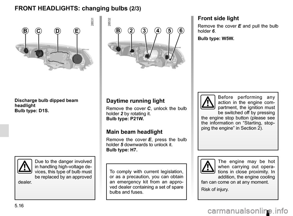
Daytime running light
Remove the cover C, unlock the bulb
holder 2 by rotating it.
Bulb type: P21W.
Main beam headlight
Remove the cover E, press the bulb
holder 5 downwards to unlock it.
Bulb type: H7.
BCDE3245B6
Front side light
Remove the cover E and pull the bulb
holder 6.
Bulb type: W5W.
Discharge bulb dipped beam
headlight
Bulb type: D1S.
Due to the danger involved
in handling high-voltage de-
vices, this type of bulb must
be replaced by an approved
dealer.
Before performing any
action in the engine com-
partment, the ignition must
be switched off by pressing
the engine stop button (please see
the information on “Starting, stop-
ping the engine” in Section 2).
Page 213 of 268
5.17
FRONT HEADLIGHTS: changing bulbs (3/3)
The bulbs are under pres-
sure and can break when
replaced.
Risk of injury.
Daytime running lights 7
Please see an authorised dealer.
Front fog lights 8
The front bumper needs to be removed;
consult an approved Dealer.
Additional lights
If you wish to fit fog lights or long range
headlights to your vehicle, consult an
approved Dealer.
Any operation on (or mo-
dification to) the electri-
cal system must be perfor-
med by an approved dealer
since an incorrect connection might
damage the electrical equipment
(harness, components and in par-
ticular the alternator). In addition,
your Dealer has all the parts requi-
red for fitting these units.
87
Page 214 of 268
5.18
REAR LIGHTS AND INDICATOR LIGHTS: changing bulbs (1/6)
5
– loosen nut 1, press down on it to
release the front of the light (move-
ment A) then remove the nut;
– from the outside, pull the light to- wards you (movement B);
– remove the bulb holder 3 by re-
leasing the clips 4. Direction indicator lights
5
Bulb type: PY21W.
Side light and brake light 6
Bulb type: P21/5W.
Refitting
To refit, proceed in the reverse order,
taking care not to damage the wiring.Five-door versions
Direction indicator lights/brake and
side lights
– Unclip the cover to access nuts 1
and 2;
– unscrew nut 2 without removing it
completely;
The bulbs are under pres-
sure and can break when
replaced.
Risk of injury.
4
6
A
B
1
2
3
Page 215 of 268
5.19
REAR LIGHTS AND INDICATOR LIGHTS: changing bulbs (2/6)
Five-door versions
(continued)
Fog lights/side lights and reversing
lights
– From the luggage compartment, unclip flap 7, then remove the
bolts 8.
– Lower the tailgate, then pull light 9
towards the rear to release it.
– Unscrew the bulb holder for the bulb concerned.
7
9
10
8
11
Reversing light 10
Bulb type: W16W.
Fog light (left or right-hand side)/
side light 11
Bulb type: P21/4W.
Page 216 of 268
5.20
Three-door versions
– Unclip the access flap;
– unscrew nuts 12 and 13;
– from the outside, remove bolt 14,
then pull on the light;
– remove the bulb holder by releasing the clips 15; 16 Side light/stop light
Bulb type: P21/5W.
17 Direction indicator light
Bulb type: PY21W.
18 Reversing light
Bulb type: P21W.
Fog light (left or right-hand side)
Undo bulb holder 19, turning it towards
the centre of the vehicle by accessing it
from underneath.
Bulb type: P21W.
The bulbs are under pres-
sure and can break when
replaced.
Risk of injury.
REAR LIGHTS AND INDICATOR LIGHTS: changing bulbs (3/6)
18
16
1712
13
14
15
19