Page 73 of 252
1.67
TRIP COMPUTER AND WARNING SYSTEM: information messages
Examples of messagesInterpreting the display selected
« PARKING BRAKE ON » Indicates that the parking brake has been applied.
« PLEASE REMOVE KEYCARD » Request to remove the RENAULT card from the reader when you leave the vehicle.
« TRACTION
CONTROL OFF » Indicates that you have deactivated the traction control function.
« TURN STEERINGWHEEL + START » Turn the steering wheel slightly whilst pressing the vehicle start button\
to unlock the steering
column.
« STEERING WHEEL NOT LOCKED » Indicates that the steering column has not been locked.
These can help in the vehicle starting phase, or give information about \
a selection or a driving status.
Examples of information messages are given in the following pages.
Page 82 of 252

1.76
éHazard warning lights
Press switch 2.
This switch activates all four direction
indicators and the side indicator lights
simultaneously. It must only be used in
an emergency to warn drivers of other
vehicles that you have had to stop in
an area where stopping is prohibited or
unexpected, or that you are obliged to
drive under special conditions.
Depending on the vehicle, the hazard
warning lights may come on auto-
matically under heavy deceleration.
You can switch them off by pressing
switch 2 once.
Direction indicators
Move stalk 1 parallel to the steering
wheel and in the direction you are going
to turn it.
One-touch mode
When driving, it is possible that the
steering wheel may not be turned suf-
ficiently to return the stalk automatically
to its starting position.
In this case, move the stick 1 to half-
way, then release it: the stalk returns to
its original point and the indicator light
flashes three times.
Horn
Press steering wheel boss A.
Headlight flasher
Pull stalk 1 towards you to flash the
headlights.
AUDIBLE AND VISUAL SIGNALS
A
21
Page 93 of 252

2.3
Hands-free RENAULT card
The RENAULT card must be inserted
in card reader 2 or in detection zone 3.
To start, depress the brake or clutch
pedal and press button 1. If a gear
is engaged, the vehicle may only be
started by depressing the clutch pedal.
Starting with the boot open in
hands-free mode
In this case, the RENAULT card must
not be located in the luggage compart-
ment.
Remote control RENAULT
card
When you get into the vehicle, insert
the RENAULT card integrated key,
pointing towards you, fully into the card
reader 2.
To start, press button 1. If a gear is en-
gaged, depress the clutch pedal to start
the vehicle.
STARTING/STOPPING THE ENGINE (1/3)
3
12
Special features
vehicles with an automatic gearbox
The lever should be in position P.
All vehicles
– If one of starting conditions is not ap- plied, the message “PRESS BRAKE
+ START” or “PRESS CLUTCH +
START” or “SELECT PARK” is dis-
played on the instrument panel;
– in some cases it will be necessary to move the steering wheel while
pressing the start button 1 to help
unlock the steering column; the mes-
sage “TURN STEERINGWHEEL +
START” warns you.
– in the event of starting the engine in very low exterior temperatures
(lower than -10°C): hold down the
clutch pedal until the engine starts.
Page 114 of 252

2.24
Electronic stability program
(ESC) with understeer control
and traction control
Electronic stability control ESC
This system helps you to keep control
of the vehicle in critical driving condi-
tions (avoiding an obstacle, loss of grip
on a bend, etc.).
Operating principle
A sensor in the steering wheel detects
the direction selected by the driver.
Other sensors throughout the vehicle
measure the actual direction.
The system compares driver input to
the actual trajectory of the vehicle and
corrects the trajectory if necessary by
controlling the braking of certain wheels
and/or engine power. In the event that
the system is engaged, indicator light
� flashes on the instrument panel.
DRIVER CORRECTION DEVICES AND AIDS (2/4)
Understeer control
This system optimises the action of the
ESC in the case of pronounced under-
steer (loss of front axle road holding).
Traction control
This system helps to limit wheelspin of
the drive wheels and to control the ve-
hicle when pulling away accelerating or
decelerating.
Operating principle
Using the wheel sensors, the system
measures and compares the speed of
the drive wheels at all times and slows
down their over-rotation. If a wheel is
starting to slip, the system brakes au-
tomatically until the drive supplied be-
comes compatible with the level of grip
under the wheel again.
The system also adjusts the engine
speed to the grip available under the
wheels, independently of the pressure
exerted on the accelerator pedal.Operating faults
When the system detects an operating
fault the message “CHECK ESC” and
warning light
© and � appear
on the instrument panel. In this case,
the ESC and traction control system
are deactivated.
Consult an approved dealer.
Disabling the traction control
system
In some situations (driving on very wet
ground: snow, mud, etc. or driving with
snow chains fitted), the system may
reduce the engine output to limit whee-
lspin.
Page 127 of 252

2.37
REVERSING CAMERA (2/2)
The screen shows a reverse image.
The frames are a representation
projected onto flat ground; this in-
formation must not be taken into
account when superimposed on a
vertical object or an object on the
ground.
Objects which appear on the edge
of the screen may be deformed.
In very bright light (snow, vehicle in
sunshine etc.), the camera vision
may be adversely affected.
If the boot is open or poorly closed,
the message “BOOT OPEN” ap-
pears and, depending on the vehi-
cle, the camera display disappears.
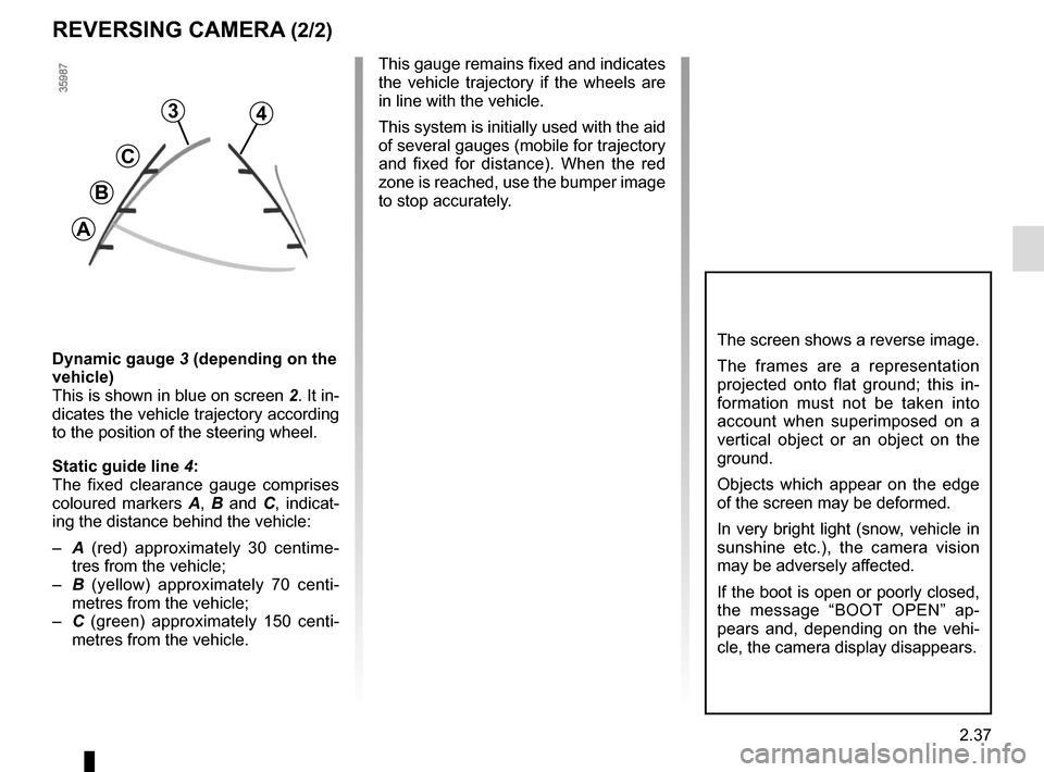
3
C
B
A
4
Dynamic gauge 3 (depending on the
vehicle)
This is shown in blue on screen 2. It in-
dicates the vehicle trajectory according
to the position of the steering wheel.
Static guide line 4:
The fixed clearance gauge comprises
coloured markers A, B and C , indicat-
ing the distance behind the vehicle:
– A (red) approximately 30 centime-
tres from the vehicle;
– B (yellow) approximately 70 centi-
metres from the vehicle;
– C (green) approximately 150 centi-
metres from the vehicle. This gauge remains fixed and indicates
the vehicle trajectory if the wheels are
in line with the vehicle.
This system is initially used with the aid
of several gauges (mobile for trajectory
and fixed for distance). When the red
zone is reached, use the bumper image
to stop accurately.
Page 162 of 252
3.32
The presence and location of this equip-
ment depends on the vehicle version.
1 Multimedia touchscreen;
2 Multimedia sockets;
3 Steering column control;
4 Voice commands;
5 Microphone.
Using the telephone
We remind you of the need
to conform to the legislation
in force concerning the use
of such equipment.
MULTIMEDIA EQUIPMENT
1
5
3
2
4
Refer to the equipment instructions
for information on how to operate
this equipment.
Page 193 of 252

5.15
Emergency spare wheel
Refer to the information on the
“Emergency spare wheel” and in-
structions on “Changing a wheel” in
Section 5.
Changing wheels around
This practice is not recommended.
Fitting new tyres
TYRES (3/3)
Snow or Winter tyres
We would recommend that these be
fitted to all four wheels to ensure that
your vehicle retains maximum adhe-
sion.
Warning : These tyres sometimes have
a specific direction of rotation and a
maximum speed index which may be
lower than the maximum speed of your
vehicle.
Studded tyres
This type of equipment may only be
used for a limited period and as laid
down by local legislation. It is neces-
sary to observe the speed specified by
current legislation.
These tyres must, at a minimum, be
fitted to the two front wheels.
Chains may only be fitted
to tyres of the same size
as those originally fitted to
your vehicle.
In all cases, we would recommend
that you contact an approved dealer
who will be able to advise you on
the choice of equipment which is
most suitable for your vehicle.
18” wheels cannot be
fitted with chains.
If you wish to fit snow
chains, you must use spe-
cial equipment .
Consult an approved Dealer.
Use in winter
Chains
For safety reasons, fitting snow
chains to the rear axle is strictly for-
bidden.
Chains cannot be fitted to tyres which
are larger than those originally fitted to
the vehicle.
For safety reasons, this op-
eration must be carried out
by a specialist.
Fitting different tyres may
change your vehicle as follows:
– it may mean that your vehicle no longer conforms to current regu-
lations;
– it may change the way it handles when cornering;
– it may cause the steering to be heavy;
– it may affect the use of snow chains.
Page 207 of 252

5.29
Number Allocation
1 Front windscreen wiper,
controls under steering
wheel
2 Front left-hand daytime
running lights,
right-hand side lights,
left-hand main beam
headlight,
right-hand dipped beam
headlight,
front fog lights
3 Interior lighting,
registration plate lighting,
fog lights
4 Right-hand side lights,
rear side lights
5 Left-hand side lights,
front side lights
FUSES (3/5)
Number Allocation
6 Dipped beams,
front right-hand daytime
running light,
left-hand side lights,
right-hand main beam
headlight
7 Left-hand dipped beam
headlight
8 Right-hand main beam
headlight
9 Left-hand main beam
headlight,
steering column controls
10 Steering column controls,
speed limiter/cruise control,
interior rear-view mirror,
belt warning module,
Parking sensor,
additional heating,
electric headlight beam
adjustment,
rear screen de-icerNumber Allocation
11 Central door locking,
rain and light sensor,
steering wheel angle
sensor,
vehicle start button,
electric rear windows
12 Courtesy light,
boot light,
air conditioning,
electric windows
13 ABS-ESC,
brake switch
14 Steering column controls,
brake switch
15 Horn
16 Rear fog lights
17 Cigarette lighter