Page 122 of 347
•Do not change the thermostat for Summer or Winter
operation. If replacement is ever necessary, install ONLY
the correct type thermostat. Other designs may result in
unsatisfactory engine coolant (antifreeze) performance,
poor gas mileage, and increased emissions.
Charge Air Cooler — Inter-Cooler
The charge air cooler is positioned in front of the radiator
and the air conditioner condenser. Air enters the engine
through the air cleaner and passes through the turbo-
charger, where it is pressurized. This pressurized air
rapidly reaches high temperature. The air is then directed
through a hose to the charge air cooler and through
another hose to the intake manifold of the engine. This
cooling process enables more efficient burning of fuel
resulting in fewer emissions.
To guarantee optimum performance of the system, keep
the surfaces of the charge air cooler, condenser and radiator
clean and free of debris. Periodically check the hoses leading to and from the charge air cooler for cracks or loose
clamps resulting in loss of pressure and reduced engine
performance.
Brake System
Brake Master Cylinder — Brake Fluid Level Check
The fluid level of the master cylinder should be checked
when performing under the hood service, or immedi-
ately if the “Brake System Warning Light” indicates
system failure.
The brake master cylinder has a translucent plastic
reservoir. On the outboard side of the reservoir, there is a
“MAX” mark and a “MIN” mark. The fluid level must be
kept within these two marks. Do not add fluid above the
full mark because leakage may occur at the cap.
With disc brakes, the fluid level can be expected to fall as
the brake linings wear. However, an unexpected drop in
fluid level may be caused by a leak and a system check
should be conducted.
120 MAINTAINING YOUR VEHICLE
Page 123 of 347
Refer to “Fluids, Lubricants, and Genuine Parts” in
“Maintaining Your Vehicle” for further information.
WARNING!
•Use only manufacturer’s recommended brake
fluid. Refer to “Fluids, Lubricants, and Genuine
Parts” in “Maintaining Your Vehicle” for further
information. Using the wrong type of brake fluid
can severely damage your brake system and/or
impair its performance. The proper type of brake
fluid for your vehicle is also identified on the
original factory installed hydraulic master cylinder
reservoir.
• To avoid contamination from foreign matter or
moisture, use only new brake fluid or fluid that has
been in a tightly closed container. Keep the master
cylinder reservoir cap secured at all times. Brake
fluid in a open container absorbs moisture from the
(Continued)
WARNING! (Continued)
air resulting in a lower boiling point. This may
cause it to boil unexpectedly during hard or pro-
longed braking, resulting in sudden brake failure.
This could result in a accident.
• Overfilling the brake fluid reservoir can result in
spilling brake fluid on hot engine parts, causing
the brake fluid to catch fire. Brake fluid can also
damage painted and vinyl surfaces, care should be
taken to avoid its contact with these surfaces.
• Do not allow petroleum based fluid to contaminate
the brake fluid. Brake seal components could be
damaged, causing partial or complete brake failure.
This could result in an accident.
5
MAINTAINING YOUR VEHICLE 121
Page 135 of 347
WARNING!
•You can be badly injured working on or around a
motor vehicle. Do only service work for which you
have the knowledge and the right equipment. If you
have any doubt about your ability to perform a service
job, take your vehicle to a competent mechanic.
• Failure to properly inspect and maintain your ve-
hicle could result in a component malfunction and
effect vehicle handling and performance. This
could cause an accident.
Additional Maintenance — B6 To B20 Biodiesel
NOTE:
• Under no circumstances should oil change intervals
exceed 8,000 miles (12 875 km) or six months, which-
ever comes first when using Biodiesel blends greater
than 5% (B5).
• The owner is required to monitor mileage for B6-B20
biodiesel, the automatic oil change indicator system
does not reflect the use of biofuels.
6
MAINTENANCE SCHEDULE 133
Page 136 of 347
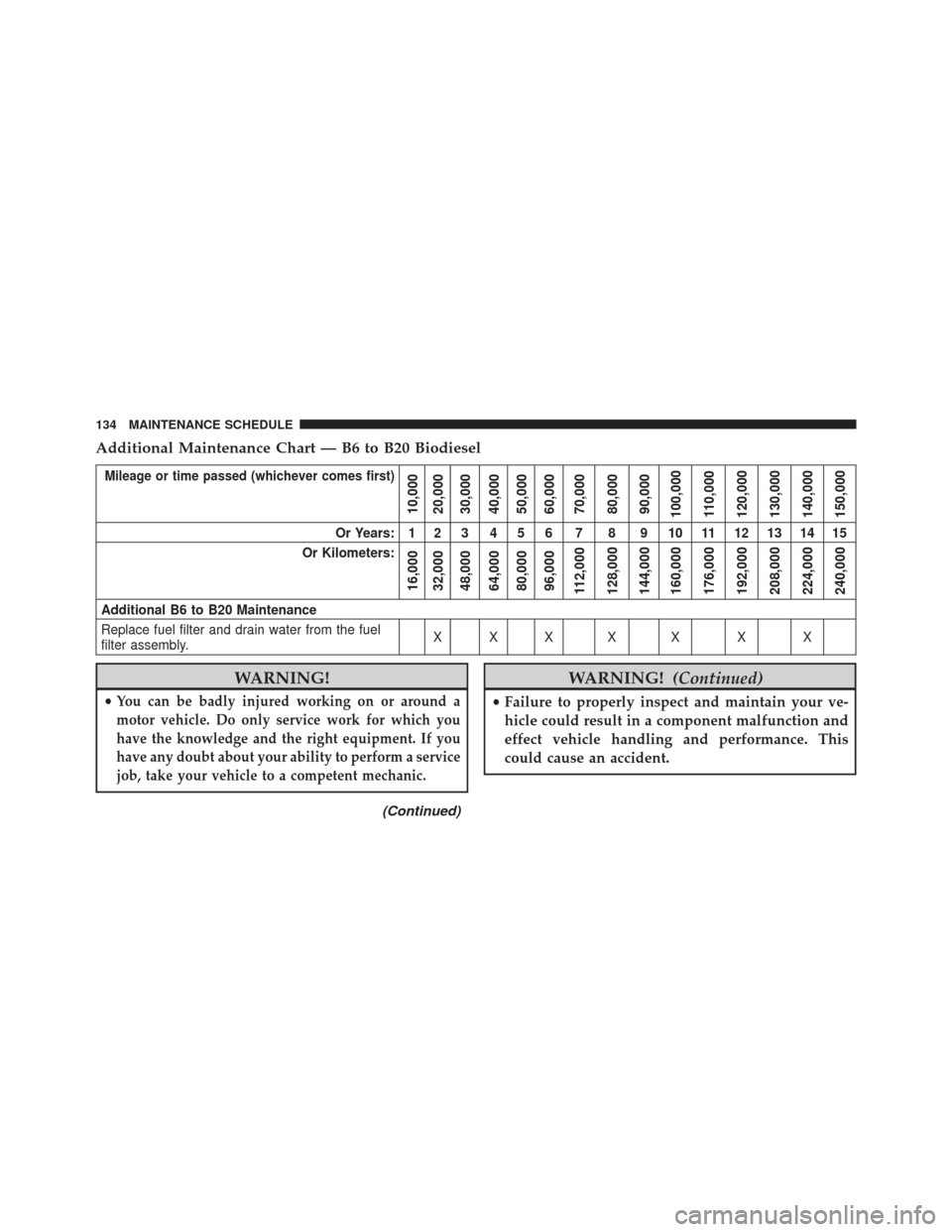
Additional Maintenance Chart — B6 to B20 Biodiesel
Mileage or time passed (whichever comes first)
10,000
20,000
30,000
40,000
50,000
60,000
70,000
80,000
90,000
100,000
110,000
120,000
130,000
140,000
150,000
Or Years: 1 2 3 4 5 6 7 8 9 10 11 12 13 14 15
Or Kilometers:
16,000
32,000
48,000
64,000
80,000
96,000
112,000
128,000
144,000
160,000
176,000
192,000
208,000
224,000
240,000
Additional B6 to B20 Maintenance
Replace fuel filter and drain water from the fuel
filter assembly. XXX X X X X
WARNING!
•You can be badly injured working on or around a
motor vehicle. Do only service work for which you
have the knowledge and the right equipment. If you
have any doubt about your ability to perform a service
job, take your vehicle to a competent mechanic.
(Continued)
WARNING! (Continued)
•Failure to properly inspect and maintain your ve-
hicle could result in a component malfunction and
effect vehicle handling and performance. This
could cause an accident.
134 MAINTENANCE SCHEDULE
Page 143 of 347
•Any chassis/suspension or tire size modifications to the
vehicle will effect the performance of the Adaptive
Cruise Control and Forward Collision Warning System.
This information cannot be erased and will stay in the
system’s memory even if the modification is removed.
This information can be retrieved by FCA US LLC, and
service and repair facilities, when servicing your vehicle.
This information may be used to determine if repair will
be covered by the New Vehicle Limited Warranty. There is a probability that the use of a “performance
chip” will prohibit the engine from starting. In this
instance, the vehicle will need to be serviced by a
authorized dealer in order to return the vehicle to it’s
factory settings.
1
INTRODUCTION 141
Page 147 of 347
WARNING!
•Do not start or run an engine in a closed garage or
confined area. Exhaust gas contains Carbon Mon-
oxide (CO) which is odorless and colorless. Carbon
Monoxide is poisonous and can cause serious in-
jury or death when inhaled.
• Keep Remote Keyless Entry (RKE) transmitters
away from children. Operation of the Remote Start
System, windows, door locks or other controls
could cause serious injury or death.
Remote Start Abort Message
The following messages will display in the EVIC/DID if
the vehicle fails to remote start or exits remote start
prematurely:
• Remote Start Aborted - Door Ajar
• Remote Start Aborted - Hood Ajar •
Remote Start Aborted - Fuel Low
• Remote Start Aborted - System Fault
The EVIC/DID message stays active until the ignition is
turned to the ON/RUN position.
To Enter Remote Start Mode
Push and release the REMOTE START button
on the RKE transmitter twice, within five sec-
onds. The parking lights will flash and the horn
will chirp twice (if programmed). In cold am-
bient temperature conditions, the diesel vehicle may
delay crank up to 30 seconds for the fuel and grid heater.
Once the vehicle has started, the engine will run for 15
minutes or 75 seconds in extreme cold and high
elevation.
2
THINGS TO KNOW BEFORE STARTING YOUR VEHICLE 145
Page 151 of 347
UNDERSTANDING YOUR INSTRUMENT PANEL
CONTENTS
�INSTRUMENT CLUSTER .................150
▫ Instrument Cluster Descriptions ...........151
� INSTRUMENT CLUSTER .................163
▫ Instrument Cluster Descriptions ...........164
� ELECTRONIC VEHICLE INFORMATION
CENTER (EVIC) ...................... .174
▫ Instrument Cluster Messages .............175
▫ Vehicle Information (Customer Information
Features) ........................... .176
� Driver Information Display
(DID) — 7” Display .....................188 ▫
Diesel Indicator Lights ..................191
▫ Cold Ambient Derate Mode Messages .......191
▫ Diesel Particulate Filter (DPF) Messages .....192
▫ Diesel Exhaust Fluid (DEF) Warning
Messages .......................... .195
▫ Diesel Exhaust Fluid (DEF) Fault Warning
Messages .......................... .196
▫ RAM Active Air System .................198
▫ Fuel Filter Life Reset ...................199
▫ Oil Life Reset ....................... .2003
Page 153 of 347
Instrument Cluster Descriptions
1. Tachometer
1. The tachometer indicates engine speed in RevolutionsPer Minute (RPM x 1000).
2. Anti-Lock Brake (ABS) Light
This light monitors the Anti-lock Brake System
(ABS). The light will turn on when the ignition
switch is turned to the ON/RUN position and
may stay on for as long as four seconds.
If the ABS light remains on or turns on while driving, it
indicates that the anti-lock portion of the brake system is
not functioning and that service is required. However,
the conventional brake system will continue to operate
normally if the BRAKE warning light is not on.
If the ABS light is on, the brake system should be serviced
as soon as possible to restore the benefits of anti-lock
brakes. If the ABS light does not turn on when the ignition switch is turned to the ON/RUN position, have
the light inspected by an authorized dealer.
3. Malfunction Indicator Light (MIL)
The Malfunction Indicator Light (MIL) is part
of an Onboard Diagnostic (OBDII) system
which monitors the emissions and engine con-
trol system. If the vehicle is ready for emissions
testing, the light will come on when the ignition is first
turned on and remain on, as a bulb check, until the
engine is started. If the vehicle is not ready for emissions
testing the light will come on when the ignition is first
turned on and remain on for 15 seconds, then blink for 5
seconds, and remain on until the vehicle is started. If the
bulb does not come on during starting, have the condi-
tion investigated promptly.
If this light comes on and remains on while driving, it
suggests a potential engine control problem and the need
for system service.
3
UNDERSTANDING YOUR INSTRUMENT PANEL 151