Page 114 of 348
,
should be checked monthly when cold and
inflated to the inflati")
INSTRUMENT CLUSTER DESCRIPTIONS
1. Tire Pressure Monitoring Telltale Light — If Equipped
Each tire, including the spare (if provided),
should be checked monthly when cold and
inflated to the inflation pressure recommended
by the vehicle manufacturer on the vehicle
placard or tire inflation pressure label. (If your vehicle
has tires of a different size than the size indicated on the
vehicle placard or tire inflation pressure label, you should
determine the proper tire inflation pressure for those
tires.)
As an added safety feature, your vehicle has been
equipped with a Tire Pressure Monitoring System
(TPMS) that illuminates a low tire pressure telltale when
one or more of your tires is significantly under-inflated.
Accordingly, when the low tire pressure telltale illumi-
nates, you should stop and check your tires as soon as
possible, and inflate them to the proper pressure. Drivingon a significantly under-inflated tire causes the tire to
overheat and can lead to tire failure. Under-inflation also
reduces fuel efficiency and tire tread life, and may affect
the vehicle’s handling and stopping ability.
Please note that the TPMS is not a substitute for proper
tire maintenance, and it is the driver ’s responsibility to
maintain correct tire pressure, even if under-inflation has
not reached the level to trigger illumination of the TPMS
low tire pressure telltale.
Your vehicle has also been equipped with a TPMS
malfunction indicator to indicate when the system is not
operating properly. The TPMS malfunction indicator is
combined with the low tire pressure telltale. When the
system detects a malfunction, the telltale will flash for
approximately one minute and then remain continuously
illuminated. This sequence will continue upon subse-
quent vehicle start-ups as long as the malfunction exists.
When the malfunction indicator is illuminated, the sys-
tem may not be able to detect or signal low tire pressure
112 UNDERSTANDING YOUR INSTRUMENT PANEL
Page 115 of 348

as intended. TPMS malfunctions may occur for a variety
of reasons, including the installation of replacement or
alternate tires or wheels on the vehicle that prevent the
TPMS from functioning properly. Always check the
TPMS malfunction telltale after replacing one or more
tires or wheels on your vehicle, to ensure that the
replacement or alternate tires and wheels allow the TPMS
to continue to function properly.
WARNING!
The TPMS has been optimized for the original
equipment tires and wheels. TPMS pressures and
warning have been established for the tire size
equipped on your vehicle. Undesirable system opera-
tion or sensor damage may result when using re-
placement equipment that is not of the same size,
type, and/or style. Aftermarket wheels can cause
(Continued)
WARNING!(Continued)
sensor damage. Do not use tire sealant from a can or
balance beads if your vehicle is equipped with a
TPMS, as damage to the sensors may result.
2. Turn Signal Indicators
The arrows will flash in unison with the exte-
rior turn signal, when using the turn signal
lever.
3. Electronic Stability Control (ESC) OFF Indicator
Light
This light indicates the Electronic Stability Con-
trol (ESC) is off.
4
UNDERSTANDING YOUR INSTRUMENT PANEL 113
Page 178 of 348
 cannot prevent
the natural laws of physics from acting on the
vehicle, nor can it increase the traction afforded by
prevailing road conditions. ESC canno")
WARNING!
•Electronic Stability Control (ESC) cannot prevent
the natural laws of physics from acting on the
vehicle, nor can it increase the traction afforded by
prevailing road conditions. ESC cannot prevent all
collisions, including those resulting from excessive
speed in turns, driving on very slippery surfaces, or
hydroplaning. ESC also cannot prevent collisions
resulting from loss of vehicle control due to inap-
propriate driver input for the conditions. Only a
safe, attentive, and skillful driver can prevent col-
lisions.The capabilities of an ESC equipped ve-
hicle must never be exploited in a reckless or
dangerous manner which could jeopardize the us-
er ’s safety or the safety of others.
(Continued)
WARNING!(Continued)
•Vehicle modifications, or failure to properly main-
tain your vehicle, may change the handling charac-
teristics of your vehicle, and may negatively affect
the performance of the ESC system. Changes to the
steering system, suspension, braking system, tire
type and size or wheel size may adversely affect ESC
performance. Improperly inflated and unevenly
worn tires may also degrade ESC performance. Any
vehicle modification or poor vehicle maintenance
that reduces the effectiveness of the ESC system can
increase the risk of loss of vehicle control, vehicle
rollover, personal injury and death.
The ESC system uses sensors installed on the car to
determine the trajectory that the driver intends to follow
and compares it with the car ’s effective trajectory. When
176 STARTING AND OPERATING
Page 183 of 348

•Vehicle modifications, or failure to properly main-
tain your vehicle, may change the handling charac-
teristics of your vehicle, and may negatively affect
the performance of th")
WARNING!(Continued)
•Vehicle modifications, or failure to properly main-
tain your vehicle, may change the handling charac-
teristics of your vehicle, and may negatively affect
the performance of the ESC system. Changes to the
steering system, suspension, braking system, tire
type and size or wheel size may adversely affect
ESC performance. Improperly inflated and un-
evenly worn tires may also degrade ESC perfor-
mance. Any vehicle modification or poor vehicle
maintenance that reduces the effectiveness of the
ESC system can increase the risk of loss of vehicle
control, vehicle rollover, personal injury and death.
This is an integral part of the ESC system and automati-
cally operates in the event of one or both drive wheels
slipping, loss of grip on wet roads (hydroplaning) and
acceleration on slippery, snowy or icy roads, etc.Depending on the slipping conditions, two different
control systems are activated:
•If the slipping involves both drive wheels, the ASR
system intervenes, reducing the power transmitted by
the engine.
•If the slipping only involves one of the drive wheels, it
also intervenes automatically, braking the wheel that is
slipping.
System Intervention
This is indicated by the flashing of the warning light on
the instrument panel, to inform the driver that the car is
in critical stability and grip conditions.
5
STARTING AND OPERATING 181
Page 186 of 348
Electronic Q2 System (E-Q2)
The�Electronic Q2�system intervenes during accelera-
tion on corners, braking the inner drive wheel and thus
increasing the traction of the outer wheel (which bears
more of the car ’s weight): the torque is thus distributed
optimally between the drive wheels in accordance with
the driving conditions and road surface, permitting par-
ticularly effective, sporty driving.
Ready Alert Brake System (RAB)
This function activates automatically if the accelerator
pedal is released rapidly, reducing the brake pad travel
(both at front and back), with the aim of preparing the
braking system and enhancing its responsiveness, thus
reducing the stopping distance in the event of subse-
quent braking.
TIRE SAFETY INFORMATION
Tire Markings
1 — U.S. DOT Safety Standards
Code (TIN)4 — Maximum Load
2 — Size Designation 5 — Maximum Pressure
3 — Service Description 6 — Treadwear, Traction and
Temperature Grades 184 STARTING AND OPERATING
Page 187 of 348
 — Metric tire sizing is based on U.S.
design standards. P-Metric tires have the letter “P”
molded into the sidewall preceding the size designa-
tion. Example: P215/65R15 9")
NOTE:
•P (Passenger) — Metric tire sizing is based on U.S.
design standards. P-Metric tires have the letter “P”
molded into the sidewall preceding the size designa-
tion. Example: P215/65R15 95H.
•European — Metric tire sizing is based on European
design standards. Tires designed to this standard have
the tire size molded into the sidewall beginning with
the section width. The letter�P�is absent from this tire
size designation. Example: 215/65R15 96H.
•LT (Light Truck) — Metric tire sizing is based on U.S.
design standards. The size designation for LT-Metric
tires is the same as for P-Metric tires except for the
letters “LT” that are molded into the sidewall preced-
ing the size designation. Example: LT235/85R16.•Temporary spare tires are designed for temporary
emergency use only. Temporary high pressure com-
pact spare tires have the letter “T” or “S” molded into
the sidewall preceding the size designation. Example:
T145/80D18 103M.
•High flotation tire sizing is based on U.S. design
standards and it begins with the tire diameter molded
into the sidewall. Example: 31x10.5 R15 LT.
5
STARTING AND OPERATING 185
Page 188 of 348
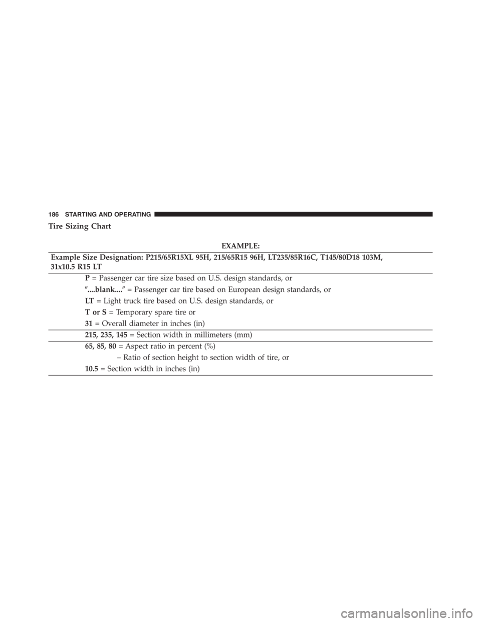
Tire Sizing Chart
EXAMPLE:
Example Size Designation: P215/65R15XL 95H, 215/65R15 96H, LT235/85R16C, T145/80D18 103M,
31x10.5 R15 LT
P= Passenger car tire size based on U.S. design standards, or
�....blank....�= Passenger car tire based on European design standards, or
LT= Light truck tire based on U.S. design standards, or
TorS= Temporary spare tire or
31= Overall diameter in inches (in)
215, 235, 145= Section width in millimeters (mm)
65, 85, 80= Aspect ratio in percent (%)
– Ratio of section height to section width of tire, or
10.5= Section width in inches (in)
186 STARTING AND OPERATING
Page 191 of 348
EXAMPLE:
DOT MA L9 ABCD 0301
DOT= Department of Transportation
– This symbol certifies that the tire is in compliance with the U.S. Department of Transportation tire
safety standards and is approved for highway use
MA= Code representing the tire manufacturing location (two digits)
L9= Code representing the tire size (two digits)
ABCD= Code used by the tire manufacturer (one to four digits)
03= Number representing the week in which the tire was manufactured (two digits)
– 03 means the 3rd week
01= Number representing the year in which the tire was manufactured (two digits)
– 01 means the year 2001
– Prior to July 2000, tire manufacturers were only required to have one number to represent the year
in which the tire was manufactured. Example: 031 could represent the 3rd week of 1981 or 1991
5
STARTING AND OPERATING 189