Page 262 of 384
 position.
2. Move the ignition switch slightly in the ON direction.
3. Turn the ignition switch")
When the ignition switch cannot be placed to the
LOCK position:1. Shift the shift lever to the P (Park) position.
2. Move the ignition switch slightly in the ON direction.
3. Turn the ignition switch to the LOCK posi- tion.
4. Remove the key if it is inserted in the ignition switch.
If the ignition switch is placed to the LOCK posi-
tion, the shift lever cannot be moved from the P
(Park) position.
The shift lever can be moved if the ignition
switch is in the ON position and the foot
brake pedal is depressed.
There is an OFF position
�1between the
LOCK and ACC positions. The OFF position
is indicated by a “1” on the key cylinder.
MANUAL TRANSMISSION (if so
equipped)
The ignition switch includes a device that helps
prevent accidental removal of the key while driv-
ing.
The key can only be removed when the ignition
switch is in the LOCK position.
In order for the steering wheel to be locked, it
must be turned about 1/8 of a turn clockwise
from the straight up position. To lock the steering wheel, place the igni-
tion switch in the LOCK position. Remove
the key. To unlock the steering wheel, in-
sert the key and turn it gently while rotating
the steering wheel slightly right and left.
IGNITION SWITCH POSITIONS
LOCK: Normal parking position (0)
OFF: (1)
The engine can be turned off without locking the
steering wheel.
ACC: (Accessories) (2)
This position activates electrical accessories
such as the radio when the engine is not running.
ON: Normal operating position (3)
This position turns on the ignition system and the
electrical accessories.
START: (4)
This position starts the engine. As soon as the
engine has started, release the key. It automati-
cally returns to the ON position.
WSD0052
Starting and driving5-9
Page 292 of 384
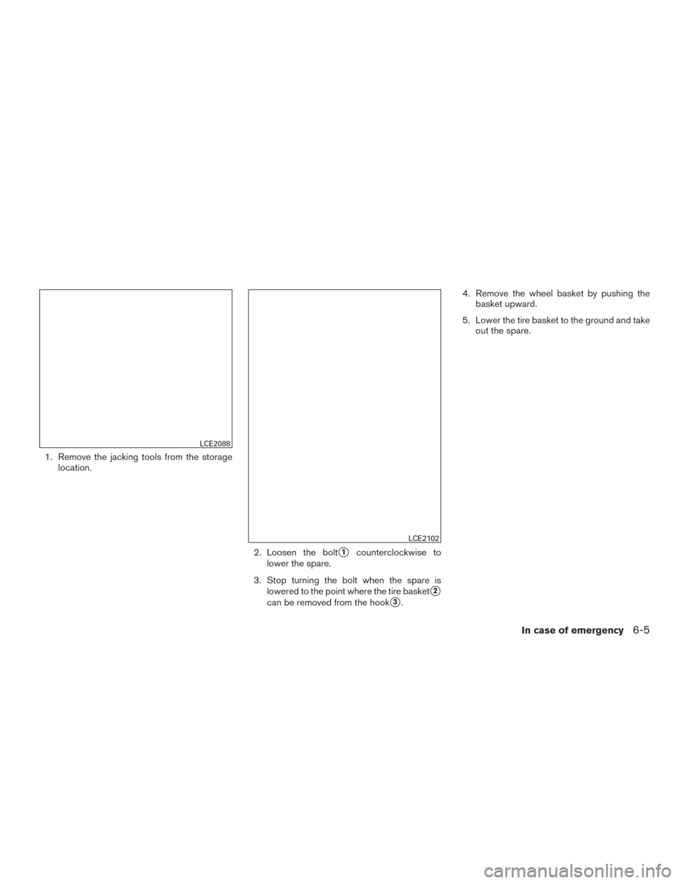
1. Remove the jacking tools from the storagelocation.
2. Loosen the bolt
�1counterclockwise to
lower the spare.
3. Stop turning the bolt when the spare is lowered to the point where the tire basket
�2
can be removed from the hook�3. 4. Remove the wheel basket by pushing the
basket upward.
5. Lower the tire basket to the ground and take out the spare.
LCE2088
LCE2102
In case of emergency6-5
Page 294 of 384

Always refer to the proper illustrations for the
correct placement and jack-up points for your
specific vehicle model and jack type.
Carefully read the caution label attached to
the jack body and the following instruc-
tions.1. Loosen each wheel nut 1 or 2 turns by turning counterclockwise with the wheel nut
wrench. Do not remove the wheel nuts
until the tire is off the ground. 2. Place the jack directly under the jack-up
point as illustrated so the top of the jack
contacts the vehicle at the jack-up point.
Align the jack head between the 2 notches in
the front or the rear as shown. Also fit the
groove of the jack head between the
notches as shown.
The jack should be used on firm and
level ground.
3. To lift the vehicle, securely hold the jack lever and rod with both hands. Carefully raise the
vehicle until the tire clears the ground. Re-
move the wheel nuts, and then remove the
tire.Installing the spare tire
The spare tire is designed for emergency
use. For additional information, refer to
“Wheels and tires” in the “Maintenance
and do-it-yourself” section of this manual.
1. Clean any mud or dirt from the surface be- tween the wheel and hub.
2. Carefully put the spare tire on and tighten the wheel nuts finger tight.
3. With the wheel nut wrench, tighten wheel nuts alternately and evenly as illustrated until
they are tight.
SCE0002WCE0048
In case of emergency6-7
Page 296 of 384
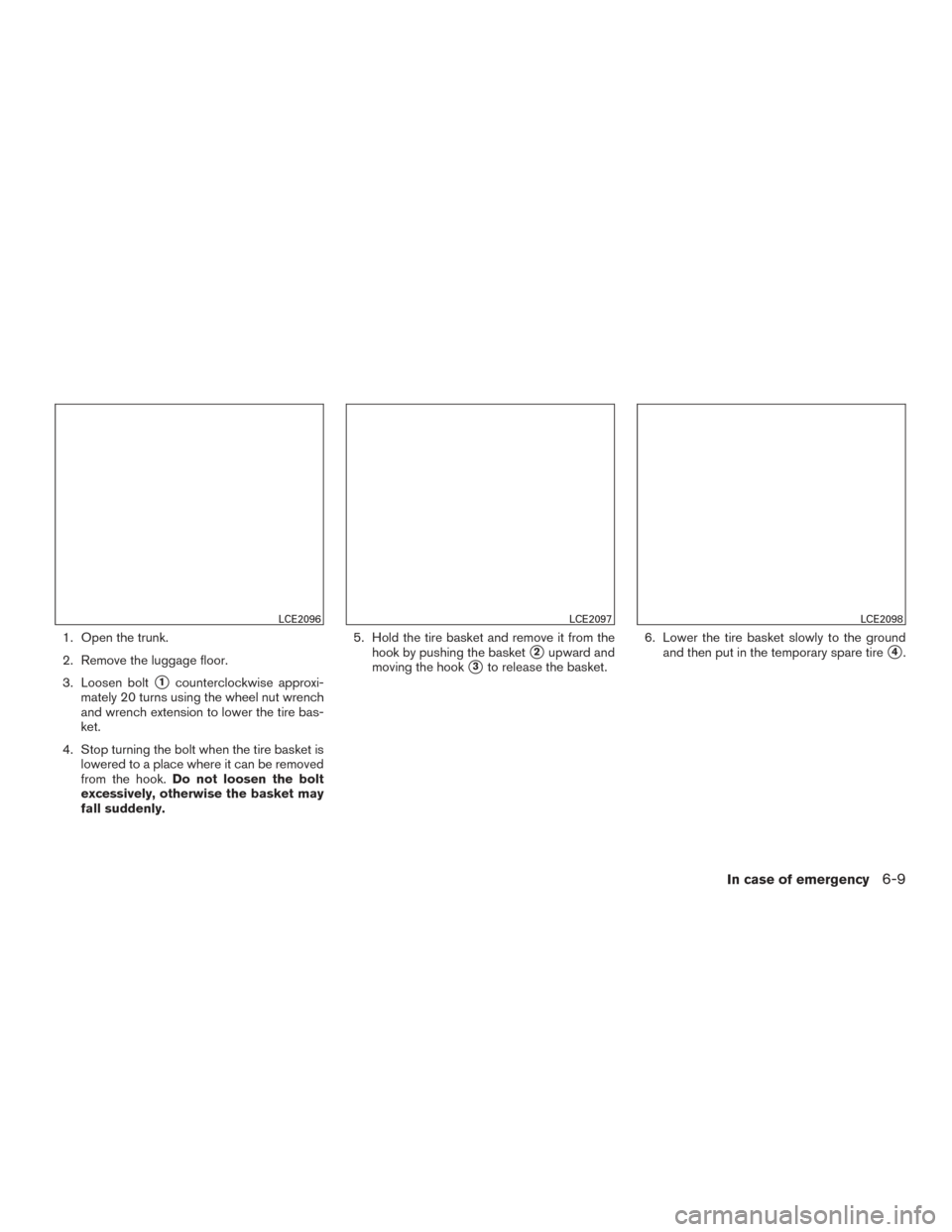
1. Open the trunk.
2. Remove the luggage floor.
3. Loosen bolt
�1counterclockwise approxi-
mately 20 turns using the wheel nut wrench
and wrench extension to lower the tire bas-
ket.
4. Stop turning the bolt when the tire basket is lowered to a place where it can be removed
from the hook. Do not loosen the bolt
excessively, otherwise the basket may
fall suddenly. 5. Hold the tire basket and remove it from the
hook by pushing the basket
�2upward and
moving the hook
�3to release the basket. 6. Lower the tire basket slowly to the ground
and then put in the temporary spare tire�4.
LCE2096LCE2097LCE2098
In case of emergency6-9
Page 297 of 384
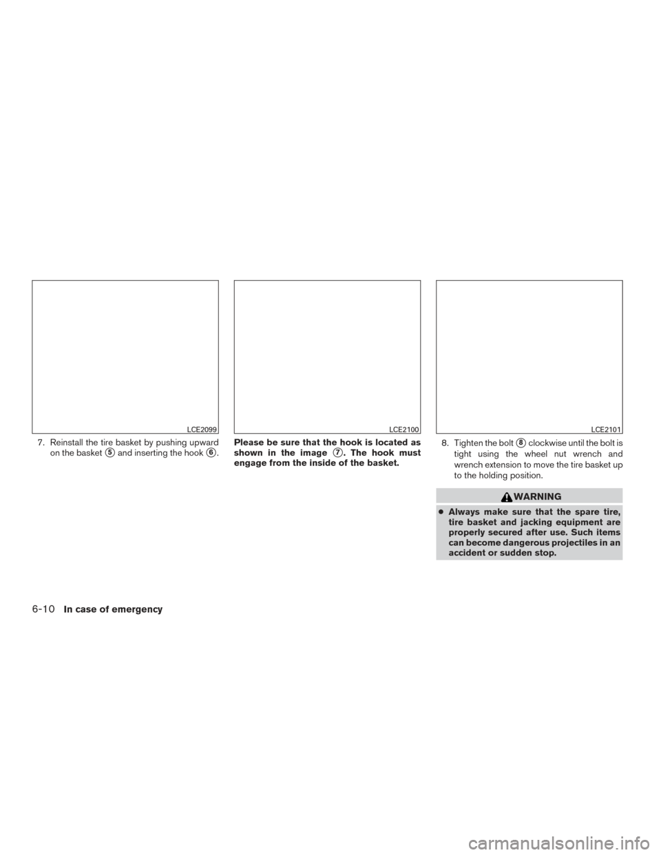
7. Reinstall the tire basket by pushing upwardon the basket
�5and inserting the hook�6. Please be sure that the hook is located as
shown in the image�7. The hook must
engage from the inside of the basket. 8. Tighten the bolt�8clockwise until the bolt is
tight using the wheel nut wrench and
wrench extension to move the tire basket up
to the holding position.
WARNING
● Always make sure that the spare tire,
tire basket and jacking equipment are
properly secured after use. Such items
can become dangerous projectiles in an
accident or sudden stop.
LCE2099LCE2100LCE2101
6-10In case of emergency
Page 322 of 384

3. Remove the oil filler cap�Bby turning it
counterclockwise.
4. Place a large drain pan under the drain plug
�A.
5. Remove the drain plug
�Awith a wrench by
turning it counterclockwise and completely
drain the oil.
If the oil filter is to be changed, remove and
replace it at this time. For additional informa-
tion, refer to “Changing engine oil filter” in
this section.
WARNING
● Prolonged and repeated contact with
used engine oil may cause skin cancer.
● Try to avoid direct skin contact with
used oil. If skin contact is made, wash
thoroughly with soap or hand cleaner as
soon as possible.
● Keep used engine oil out of reach of
children.
CAUTION
● Be careful not to burn yourself. The en-
gine oil may be hot.
● Waste oil must be disposed of properly.
● Check your local regulations.
6. Clean and reinstall the drain plug
�Aand a
new washer. Securely tighten the drain plug
�Awith a wrench. Do not use excessive
force.
Drain plug tightening torque: 22 - 29 ft-lb (29 - 39 N·m)
7. Refill engine with recommended oil through the oil filler opening, then install the oil filler
cap
�Bsecurely.
For additional information, refer to “Recom-
mended fluids/lubricants and capacities” in
the “Technical and consumer information”
section of this manual for drain and refill
capacity.
The drain and refill capacity depends on the
oil temperature and drain time. Use these
specifications for reference only. Always use
the dipstick to determine when the proper
amount of oil is in the engine. 8. Start the engine. Check for leakage around
the drain plug
�Aand oil filter. Correct as
required.
9. Turn the engine off and wait more than 10 minutes. Check the oil level with the
dipstick. Add engine oil if necessary.
Maintenance and do-it-yourself8-11
Page 323 of 384

CHANGING ENGINE OIL FILTER
1. Park the vehicle on a level surface and applythe parking brake.
2. Turn the engine off.
3. Place a large drain pan under the oil filter
�B. 4. Loosen the oil filter with an oil filter wrench
by turning it counterclockwise. Then remove
the oil filter by turning it by hand.
CAUTION
Be careful not to burn yourself. The engine
oil may be hot.
5. Wipe the engine oil filter sealing surface with a clean rag.
CAUTION
Be sure to remove any old gasket material
remaining on the sealing surface of the
engine. Failure to do so could lead to
engine damage.
6. Coat the gasket on the new filter with clean engine oil .
7. Screw on the oil filter until a slight resistance is felt, then tighten an additional 2/3 turn.
Oil filter tightening torque: 11 - 15 ft-lbs (15 - 20 N·m)
8. Start the engine and check for leakage around the oil filter. Correct as required.
9. Turn the engine off and wait more than 10 minutes. Check the oil level. Add engine
oil by removing the oil filler cap
�Aif neces-
sary.
CAUTION
● NISSAN recommends using Genuine
NISSAN CVT Fluid NS-3 ONLY in
NISSAN CVTs. Do not mix with other
fluids.
● Do not use Automatic transmission
fluid (ATF) or Manual transmission fluid
in a NISSAN CVT, as it may damage the
CVT. Damage caused by the use of flu-
ids other than recommended is not cov-
ered under NISSAN’s New Vehicle Lim-
ited Warranty.
● Using fluids that are not equivalent to
Genuine NISSAN CVT Fluid NS-3 may
also damage the CVT. Damage caused
by the use of fluids other than as recom-
mended is not covered under NISSAN’s
New Vehicle Limited Warranty.
When checking or replacement of CVT fluid is
required, we recommend your NISSAN dealer for
servicing.
LDI2365
CONTINUOUSLY VARIABLE
TRANSMISSION (CVT) FLUID (if so
equipped)
8-12Maintenance and do-it-yourself
Page 337 of 384

Note:
Changes or modifications not expressly ap-
proved by the party responsible for compli-
ance could void the user’s authority to op-
erate the equipment.
For Canada:
This device complies with Industry Canada
licence-exempt RSS standard(s) . Opera-
tion is subject to the following two condi-
tions: (1) this device may not cause inter-
ference, and (2) this device must accept any
interference, including interference that
may cause undesired operation of the de-
vice.
HEADLIGHTS
Replacing the halogen headlight bulb
The headlight is a semi-sealed beam type which
uses a replaceable headlight (halogen) bulb.
They can be replaced from inside the engine
compartment without removing the headlight as-
sembly.
CAUTION
●High-pressure halogen gas is sealed in-
side the bulb. The bulb may break if the
glass envelope is scratched or the bulb
is dropped. ●
Aiming should not be necessary after
replacing the bulb. When aiming adjust-
ment is necessary, contact a NISSAN
dealer.
● Do not leave the headlight assembly
open without a bulb installed for a long
period of time. Dust, moisture, smoke,
etc. entering the headlight body may
affect bulb performance. Remove the
bulb from the headlight assembly just
before a replacement bulb is installed.
● Only touch the base when handling the
bulb. Never touch the glass envelope.
Touching the glass could significantly
affect bulb life and/or headlight
performance.
● Use the same number and wattage as
shown in the chart.
1. Disconnect the battery negative cable.
2. Disconnect the electrical connector from the rear end of the bulb.
3. Rotate the retaining pin counterclockwise to loosen it.
4. Remove the headlight bulb. Do not shake or rotate the bulb when removing it.
LDI2240
LIGHTS
8-26Maintenance and do-it-yourself