Page 128 of 457

The autolight system allows the headlights to be
set so they turn on and off automatically. The
autolight system can:● Turn on the headlights, front parking, tail,")
Autolight system (if so equipped)
The autolight system allows the headlights to be
set so they turn on and off automatically. The
autolight system can:● Turn on the headlights, front parking, tail,
license plate and instrument panel lights au-
tomatically when it is dark.
● Turn off all the lights when it is light.
● Keep all the lights on for a period of time after
you place the ignition switch in the OFF
position and all doors are closed. To turn on the autolight system:
1. Turn the headlight switch to the AUTO posi- tion
�1.
2. Place the ignition switch in the ON position.
3. The autolight system automatically turns the headlights on and off.
Initially, if the ignition switch is placed in the OFF
position and a door is opened and left open, the
headlights remain ON for a period of time. If
another door is opened while the headlights are
on, then the timer is reset.
To turn the autolight system off, turn the switch to
the OFF,
,orposition. Be sure you do not put anything on top of
the autolight sensor
�1located on the top
side of the instrument panel. The autolight
sensor controls the autolight; if it is cov-
ered, the autolight sensor reacts as if it is
dark out and the headlights will illuminate.
If this occurs while parked with the engine
off and the ignition switch placed in the ON
position, your vehicle’s battery could be-
come discharged.
WIC1251LIC0836
2-34Instruments and controls
Page 130 of 457
INSTRUMENT BRIGHTNESS
CONTROL
The instrument brightness control operates when
the headlight control switch is in
the
,or AUTO position (with auto-
lights activated) .
Turn the control to adjust the brightness of instru-
ment panel lights when driving at night.
TURN SIGNAL SWITCH
Turn signal
�1Move the lever up or down to signal the
turning direction. When the turn is com-
pleted, the turn signal cancels automatically.
Lane change signal
�2Move the lever up or down until the turn
signal begins to flash, but the lever does not
latch, to signal a lane change. Hold the lever
until the lane change is completed.
Move the lever up or down until the turn
signal begins to flash, but the lever does not
latch, and release the lever. The turn signal
will automatically flash three times.
Choose the appropriate method to signal a lane
change based on road and traffic conditions.
WIC1506WIC1253
2-36Instruments and controls
Page 137 of 457
The power outlets are for powering electrical
accessories such as cellular telephones.
The power outlets located on the driver’s side of
the instrument panel is powered only when the
ignition switch is placed in the ACC or ON posi-
tion.
The power outlets located on the passenger’s
side of the instrument panel, and in the 2nd row
are powered only when the ignition switch is
placed in the ACC or ON position.
Open the cap to use a power outlet.
Front row
WIC1404
2nd row (if so equipped)
WIC0643
Inside center armrest (if so equipped)
LIC0618
Instruments and controls2-43
Page 140 of 457

Do not use the outlet located in the truck box with
accessories that exceed 120 volt. Do not use
double adapters or more than one electrical ac-
cessory.
CAUTION
●Operation of the 120 volt system with
the ignition in the ON position and the
engine not running (idle) will drain the
battery charge. This could lead to a
dead battery or no start condition.
● The outlet and plug may be hot during
or immediately after use.
● Use power outlets with the engine run-
ning to avoid discharging the vehicle
battery.
● Do not use double adaptors or more
than one electrical accessory.
● Avoid using power outlets when the air
conditioner, headlights or rear window
defroster is on.
● Before inserting or disconnecting a
plug, be sure the electrical accessory
being used is turned OFF. ●
Push the plug in as far as it will go. If
good contact is not made, the plug may
overheat or the internal temperature
fuse may open.
● When not in use, be sure to close the
cap. Do not allow water or any other
liquid to contact the outlet.
INSTRUMENT PANEL STORAGE
TRAYS
WARNING
Do not place sharp objects in the trays to
help prevent injury in an accident or sud-
den stop.
The rubber mats can be removed for cleaning.
Side tray
LIC0565
STORAGE
2-46Instruments and controls
Page 149 of 457
1. Window lock button
2. Power door lock switch
3. Front passenger side automatic switch
4. Right rear passenger window switch
5. Left rear passenger window switch
6. Driver side automatic switch
Driver’s side power window switch
The driver’s side control panel is equipped with
switches to open or close the front and rear
passenger windows.
To open a window, push the switch and hold it
down. To close a window, pull the switch and
hold it up. To stop the opening or closing function
at any time, simply release the switch.
Front passenger’s power window
switch
The passenger’s window switch operates only
the corresponding passenger’s window. To open
the window, push the switch and hold it down
�1.
To close the window, pull the switch up
�2.
WIC0845LIC0580
Instruments and controls2-55
Page 171 of 457
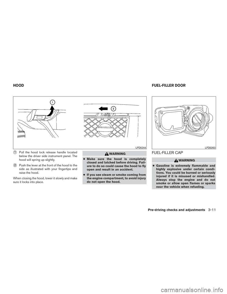
�1Pull the hood lock release handle located
below the driver side instrument panel. The
hood will spring up slightly.
�2Push the lever at the front of the hood to the
side as illustrated with your fingertips and
raise the hood.
When closing the hood, lower it slowly and make
sure it locks into place.
WARNING
● Make sure the hood is completely
closed and latched before driving. Fail-
ure to do so could cause the hood to fly
open and result in an accident.
● If you see steam or smoke coming from
the engine compartment, to avoid injury
do not open the hood.
FUEL-FILLER CAP
WARNING
● Gasoline is extremely flammable and
highly explosive under certain condi-
tions. You could be burned or seriously
injured if it is misused or mishandled.
Always stop the engine and do not
smoke or allow open flames or sparks
near the vehicle when refueling.
LPD0244LPD0263
HOOD FUEL-FILLER DOOR
Pre-driving checks and adjustments3-11
Page 173 of 457

To remove the fuel-filler cap:1. Turn the fuel-filler cap counterclockwise to remove.
2. Loop the tether strap around the hook
�1
while refueling.
To install the fuel-filler cap: 1. Insert the fuel-filler cap straight into the fuel- filler tube.
2. Turn the fuel-filler cap clockwise until a single click is heard.
Loose Fuel Cap warning
The LOOSE FUEL CAP warning appears in the
odometer when the fuel-filler cap is not tightened
correctly after the vehicle has been refueled. It
may take a few driving trips for the message to be
displayed. To turn off the warning, perform the
following:
1. Remove and install the fuel-filler cap as pre- viously described as soon as possible.
2. Tighten the fuel-filler cap until it clicks. 3. Press the loose fuel cap warning reset but-
ton
�Aon the instrument panel located be-
hind the steering wheel for about 1 second
to turn off the LOOSE FUEL CAP warning
�Bafter tightening the fuel-filler cap.
LPD0325LRS2005
Pre-driving checks and adjustments3-13
Page 214 of 457

Air recirculation
Push the air recirculation buttonto recir-
culate interior air inside the vehicle. Push the
AUTO button to return to automatic mode.
The air recirculation button will not be activated
when the air conditioner is in DEF, floor, or
floor/defrost mode.
Fresh air intake (if so equipped)
Press thefresh air intake button to draw
outside air into the passenger compartment.
The
indicator light on the button will come
on.
Air flow control
Press the air flow control buttons to manually
control air flow and select the air outlet:
— Air flows from center and side
vents.
— Air flows from center and sidevents and foot outlets.
— Air flows mainly from foot outlets.
— Air flows from defroster and footoutlets.
— Air flows from defroster outlets.
To turn system off
Press the/OFF button.
Outside mirror defroster switch (if so
equipped)
For additional information about the outside mir-
ror defroster switch, refer to “Rear window and
outside mirror (if so equipped) defroster switch”
in the “Instruments and controls” section of this
manual.
OPERATING TIPS
●When the engine coolant temperature and
outside air temperature are low, the air flow
from the foot outlets may not operate for a
maximum of 150 seconds. However, this is
not a malfunction. After the coolant tempera-
ture warms up, air flow from the foot outlets
will operate normally. The sunload sensor
�1, located on the top center
of the instrument panel, helps the system main-
tain a constant temperature. Do not put anything
on or around this sensor.
LIC0836
4-26Monitor, climate, audio, phone and voice recognition systems
 .
Turn the control to adjust the br")