Page 175 of 457
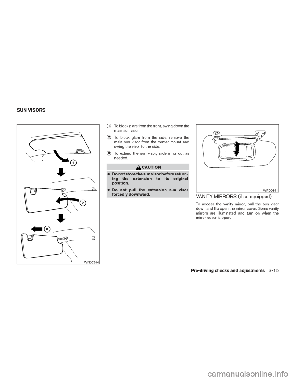
�1To block glare from the front, swing down the
main sun visor.
�2To block glare from the side, remove the
main sun visor from the center mount and
swing the visor to the side.
�3To extend the sun visor, slide in or out as
needed.
CAUTION
● Do not store the sun visor before return-
ing the extension to its original
position.
● Do not pull the extension sun visor
forcedly downward.
VANITY MIRRORS (if so equipped)
To access the vanity mirror, pull the sun visor
down and flip open the mirror cover. Some vanity
mirrors are illuminated and turn on when the
mirror cover is open.
WPD0344
WPD0141
SUN VISORS
Pre-driving checks and adjustments3-15
Page 176 of 457

Use the night position�1to reduce glare from
the headlights of vehicles behind you at night.
Use the day position
�2when driving in daylight
hours.
WARNING
Use the nig")
REARVIEW MIRROR (if so equipped)
Use the night position�1to reduce glare from
the headlights of vehicles behind you at night.
Use the day position
�2when driving in daylight
hours.
WARNING
Use the night position only when neces-
sary, because it reduces rear view clarity.
AUTOMATIC ANTI-GLARE
REARVIEW MIRROR (if so equipped)
The inside mirror is designed so that it automati-
cally dims during night time conditions and ac-
cording to the intensity of the headlights of the
vehicle following you. The automatic anti-glare
feature is activated when the ignition switch is in
the ON position.
The indicator light will illuminate when the auto-
matic anti-glare feature is operating.
NOTE:
Do not hang any objects over the sensors
�1or apply glass cleaner to the sensors.
Doing so will reduce the sensitivity of the
sensors, resulting in improper operation.
Type A (if so equipped)
With the ignition switch placed in the ON posi-
tion, press the
button as described:
● To turn off the anti-glare feature, press
the
button. The indicator light will turn
off.
● To turn on the anti-glare feature, press
the
button again. The indicator light
will turn on.
The indicator light will illuminate when the auto-
matic anti-glare feature is operating.
WPD0126
Type A (if so equipped)
LPD0446
MIRRORS
3-16Pre-driving checks and adjustments
Page 177 of 457
 , refer
to “Compass display” in the “Instruments and
controls” section of this manual.
Type B (if so equipp")
For additional information about the compass
and compass features
�2(if so equipped) , refer
to “Compass display” in the “Instruments and
controls” section of this manual.
Type B (if so equipped)
With the ignition switch in the ON position, press
the
button as described:
● To turn off the automatic anti-glare feature,
press the
button. The indicator light
will turn off.
● To turn on the automatic anti-glare feature,
press the
button again. The indicator
light will turn on.
The indicator light
�2will illuminate when the
automatic anti-glare feature is operating.
OUTSIDE MIRRORS
WARNING
● Objects viewed in the outside mirror on
the passenger side are closer than they
appear. Be careful when moving to the
right. Using only this mirror could cause
an accident. Use the inside mirror or
glance over your shoulder to properly
judge distances to other objects.
● Do not adjust the mirrors while driving.
You could lose control of your vehicle
and cause an accident.
Type B (if so equipped)
WPD0331
Pre-driving checks and adjustments3-17
Page 178 of 457
Manual control type (if so equipped)
The outside mirror can be moved in any direction
for a better rear view.
Electric control type (if so equipped)
The outside mirror remote control will operate
only when the ignition switch is placed in the
ACC or ON position.
Move the small switch
�1to select the right or left
mirror. Move the large switch
�2to adjust each
mirror to the desired position.
Trailer tow mirrors (if so equipped)
WARNING
Objects viewed in the convex portion of
the trailer tow mirror are closer than they
appear. Be careful when changing lanes or
turning. Using only the convex mirror
could cause an accident. Use the other
mirrors or glance over your shoulder to
properly judge distances to other objects.
Use the outside mirror remote control to adjust
the top portion of the trailer tow mirror.
WPD0170LPD0237LPD0279
3-18Pre-driving checks and adjustments
Page 179 of 457
The lower portion of the trailer tow mirror can be
moved manually in any direction for a better rear
view.Pull the trailer tow mirror outward to extend it to
the desired position for better visibility while tow-
ing a trailer.
WARNING
Do not extend or retract mirrors while driv-
ing. You may lose control of your vehicle
and cause an accident.
CAUTION
Driving in tight spaces with mirrors ex-
tended may cause damage to the vehicle.
Manual folding outside mirrors (if so
equipped)
Pull the outside mirror toward the door to fold it.
LPD0268
Type A (if so equipped)
LPD0259
Pre-driving checks and adjustments3-19
Page 180 of 457
Power folding outside mirrors (if so
equipped)
CAUTION
Do not manually fold the power folding
mirrors. Manually folding the mirrors can
damage the mirrors.
Push the switch to open or close the mirrors. If one of the mirrors are manually operated or
bumped, the mirror body can become loose at
the pivot point. To correct electronic mirror op-
eration, cycle the mirrors by pushing the bottom
of the switch until completely closed, then push
the top of the switch until the mirrors are in the
open position.
Heated mirrors (if so equipped)
Some outside mirrors can be heated to defrost,
defog, or de-ice for improved visibility. For addi-
tional information, refer to “Rear window and
outside mirror (if so equipped) defroster switch”
in the “Instruments and controls” section of this
manual.
Type B (if so equipped)
LPD0269LPD2316
3-20Pre-driving checks and adjustments
Page 186 of 457

MEMORY STORAGE FUNCTION
Two positions for the driver’s seat, accelerator
and brake pedals, and outside mirrors can be
stored in the automatic drive positioner memory.
Follow these procedures to use the memory sys-
tem.1. Place the shift lever in the P (Park) position.
2. Place the ignition switch in the ON position.
3. Adjust the driver’s seat, accelerator and brake pedals, and outside mirrors to the
desired positions by manually operating
each adjusting switch. For additional infor-
mation, refer to “Seats” in the “Safety— Seats, seat belts and supplemental restraint
system” section of this manual and “Pedal
position adjustment” and “Outside mirrors”
in this section.
During this step, do not place the ignition
switch in any position other than ON.
4. Push the SET switch and, within 5 seconds, push the memory switch (1 or 2) .
The indicator light for the pushed memory
switch will come on and stay on for approxi-
mately 5 seconds after pushing the switch.
After the indicator light goes off, the se-
lected positions are stored in the selected
memory (1 or 2) .
If a new memory is stored in the same memory
switch, the previous memory will be deleted.
Linking a key fob to a stored memory
position
Each key fob can be linked to a stored memory
position (memory switch 1 or 2) with the follow-
ing procedure. 1. Follow the steps for storing a memory posi- tion.
2. While the indicator light for the memory switch being set is illuminated for 5 sec-
onds, press the
button on the key fob. The indicator light will blink. After the indica-
tor light goes off, the key fob is linked to that
memory setting.
With the key removed from the ignition switch,
press the
button on the key fob. The driv-
er’s seat, accelerator and brake pedals, and out-
side mirrors will move to the memorized position.
NOTE:
If a new memory position is saved to the
memory switch, the key fob automatically
re-links.
Confirming memory storage
● Place the ignition switch in the ON position
and push the SET switch. If the main memory
has not been stored, the indicator light will
come on for approximately 0.5 seconds.
When the memory has stored the position,
the indicator light will stay on for approxi-
mately 5 seconds.
● If the battery cable is disconnected, or if the
fuse opens, the memory storage function will
be canceled and must be restarted before a
stored memory position can be set again.
Drive the vehicle over 25 MPH (40 km/h) to
restart the memory storage function. You
can also restart the memory storage function
using the following procedure.
LPD0260
3-26Pre-driving checks and adjustments
Page 187 of 457

1. Connect the battery cable or replace thefuse.
2. Open and close the driver’s door more than two times with the ignition switch in the
LOCK position.
Once the memory storage function has been
restarted, you can store a memory position.
For additional information, refer to “Memory
storage function” in this section.
Selecting the memorized position
Set the shift lever to the P (Park) position, then: ● Within 45 seconds of opening the driver’s
door, push the memory switch (1 or 2) or
● Place the ignition switch in the ON position
and push the memory switch (1 or 2) .
The driver’s seat, accelerator and brake pedals,
and outside mirrors will move to the memorized
position with the indicator light blinking, and then
the light will stay on for approximately 5 seconds.
ENTRY/EXIT FUNCTION
This system is designed so that the driver’s seat
will automatically move when the shift lever is
placed in the P (Park) position. This allows the
driver to get into and out of the driver’s seat more
easily. The driver’s seat will slide backward:
● When the key is removed from the ignition
switch and the driver’s door is opened.
● When the driver’s door is opened with the
ignition switch placed in the LOCK position.
● When the ignition switch is turned from
ACC to LOCK with the driver’s door open.
The driver’s seat will return to the previous posi-
tion: ● When the key is inserted into the ignition
switch and the driver’s door is closed.
● When the driver’s door is closed with the
ignition switch placed in the LOCK position.
● When the ignition switch is turned from
ACC to ON while the shift lever is in the P
(Park) position.
The entry/exit function can be adjusted or can-
celed. See your NISSAN dealer.
Restarting the entry/exit function
If the battery cable is disconnected or if the fuse
opens, the entry/exit function will be disabled.
Drive the vehicle over 25 MPH (40 km/h) to
restart the entry/exit function. You can also restart
the entry/exit function using the following proce-
dure. 1. Connect the battery cable or replace the
fuse.
2. Open and close the driver’s door more than two times with the ignition switch in the
LOCK position.
The entry/exit function should now work properly.
SYSTEM OPERATION
The automatic drive positioner system will not
work or will stop operating under the following
conditions: ● When the vehicle speed is above 4 MPH
(7 km/h).
● When any of the memory switches are
pushed while the automatic drive positioner
is operating.
● When the adjusting switch for the driver’s
seat is turned on while the automatic drive
positioner is operating.
● When the seat has already been moved to
the memorized position.
● When no seat position is stored in the
memory switch.
● When the shift lever is moved from P (Park)
to any other position.
Pre-driving checks and adjustments3-27

The outside mirror can be moved in any direction
for a better rear view.
Electric control type (if so equipped)
The outside mirror remote control will operate
only")


CAUTION
Do not manually fold the power folding
mirrors. Manually folding the mirrors can
damage the mirrors.
Push the switch to open or close the mirrors")