Page 95 of 322
2-20Instruments and controls
warning. For more information, see “Extended
storage fuse switch” (P.8-21) .
SIC4538
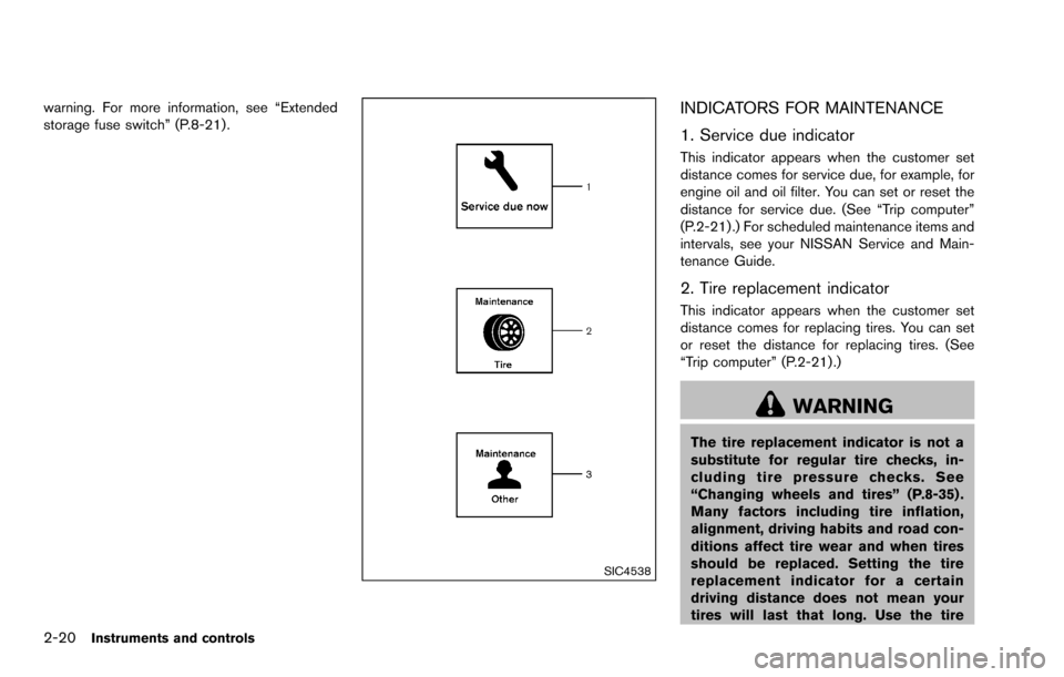
INDICATORS FOR MAINTENANCE
1. Service due indicator
This indicator appears when the customer set
distance comes for service due, for example, for
engine oil and oil filter. You can set or reset the
distance for service due. (See “Trip computer”
(P.2-21) .) For scheduled maintenance items and
intervals, see your NISSAN Service and Main-
tenance Guide.
2. Tire replacement indicator
This indicator appears when the customer set
distance comes for replacing tires. You can set
or reset the distance for replacing tires. (See
“Trip computer” (P.2-21) .)
WARNING
The tire replacement indicator is not a
substitute for regular tire checks, in-
cluding tire pressure checks. See
“Changing wheels and tires” (P.8-35) .
Many factors including tire inflation,
alignment, driving habits and road con-
ditions affect tire wear and when tires
should be replaced. Setting the tire
replacement indicator for a certain
driving distance does not mean your
tires will last that long. Use the tire
Page 96 of 322
replacement indicator as a guide only
and always perform regular tire checks.
Failure to perform regular tire checks,
including tire pressure checks could
result in tire failure. Serious vehicle
damage could occur and may lead to a
collision, which could result in serious
personal injury or death.
3. “Other” indicator
This indicator appears when the customer set
distance comes for checking or replacing
maintenance items other than the engine oil, oil
filter and tires. Other maintenance items can
include such things as air filter or tire rotation.
You can set or reset the distance for checking or
replacing the items. (See “Trip computer” (P.2-
21) .) For scheduled maintenance items and
intervals, see your NISSAN Service and Main-
tenance Guide.
SIC4551
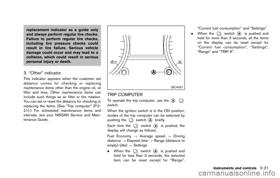
TRIP COMPUTER
To operate the trip computer, use the*Aswitch.
When the ignition switch is in the ON position,
modes of the trip computer can be selected by
pushing the
switch*Abriefly.
Each time the
switch*Ais pushed, the
display will change as follows:
Fuel Economy ?Average speed ?Driving
distance ?Elapsed time ?Range (distance to
empty) (dte) ?Settings
. When the
switch*Ais pushed and
held for less than 3 seconds, the selected
item can be reset except for “Range”, “Current fuel consumption” and “Settings”.
. When the
switch*Ais pushed and
held for more than 3 seconds, all the items
on the display can be reset except for
“Current fuel consumption”, “Settings”,
“Range” and “TRIP A”.
Instruments and controls2-21
Page 101 of 322
2-26Instruments and controls
alarm will activate.)
How to stop an activated alarm
The alarm will stop by unlocking a door by
pushing the unlock buttonon the key fob, or
using the key. The alarm will not stop if the
ignition switch is turned to the ACC or ON
position.
If the system does not operate as de-
scribed above, have it checked by a
NISSAN dealer.
NISSAN VEHICLE IMMOBILIZER SYS-
TEM
The NISSAN Vehicle Immobilizer System will not
allow the engine to start without the use of the
registered key.
If the engine fails to start using the registered
key, it may be due to interference caused by
another registered key, an automated toll road
device or automated payment device on the key
ring. Restart the engine using the following
procedures:
1. Leave the ignition switch in the ON position for approximately 5 seconds.
2. Turn the ignition switch to the OFF or LOCK position and wait approximately 10 seconds.
3. Repeat step 1 and 2 again. 4. Restart the engine while holding the device
(which may have caused the interference)
separate from the registered key.
If this procedure allows the engine to start,
NISSAN recommends placing the regis-
tered key on a separate key ring to avoid
interference from other devices.
Statement related to section 15 of FCC
rules for NISSAN Vehicle Immobilizer
System (CONT ASSY-BCM. ANT ASSY-
IMMOBILISER)
FCC Notice:
This device complies with Part 15 of the
FCC Rules. Operation is subject to the
following two conditions: (1) This device
may not cause harmful interference, and
(2) this device must accept any interfer-
ence received, including interference that
may cause undesired operation.
NOTE:
Changes or modifications not expressly
approved by the party responsible for
compliance could void the user’s authority
to operate the equipment.SIC2045
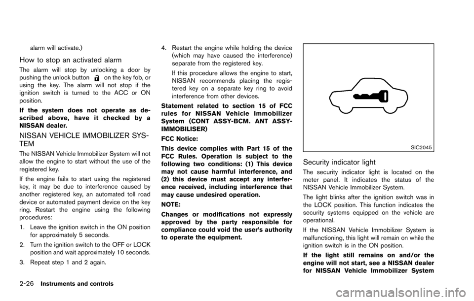
Security indicator light
The security indicator light is located on the
meter panel. It indicates the status of the
NISSAN Vehicle Immobilizer System.
The light blinks after the ignition switch was in
the LOCK position. This function indicates the
security systems equipped on the vehicle are
operational.
If the NISSAN Vehicle Immobilizer System is
malfunctioning, this light will remain on while the
ignition switch is in the ON position.
If the light still remains on and/or the
engine will not start, see a NISSAN dealer
for NISSAN Vehicle Immobilizer System
Page 104 of 322
SIC3480
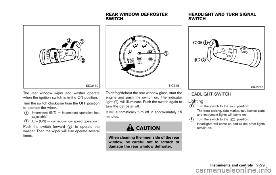
The rear window wiper and washer operate
when the ignition switch is in the ON position.
Turn the switch clockwise from the OFF position
to operate the wiper.
*1Intermittent (INT) — intermittent operation (not
adjustable)
*2Low (ON) — continuous low speed operation
Push the switch forward*3to operate the
washer. Then the wiper will also operate several
times.
SIC3481
To defog/defrost the rear window glass, start the
engine and push the switch on. The indicator
light
*1will illuminate. Push the switch again to
turn the defroster off.
It will automatically turn off in approximately 15
minutes.
CAUTION
When cleaning the inner side of the rear
window, be careful not to scratch or
damage the rear window defroster.
SIC2745
HEADLIGHT SWITCH
Lighting
*1Turn the switch to theposition:
The front parking, side marker, tail, license plate
and instrument lights will come on.
*2Turn the switch to theposition:
Headlights will come on and all the other lights
remain on.
Instruments and controls2-29
REAR WINDOW DEFROSTER
SWITCH HEADLIGHT AND TURN SIGNAL
SWITCH
Page 105 of 322
2-30Instruments and controls
SIC3484
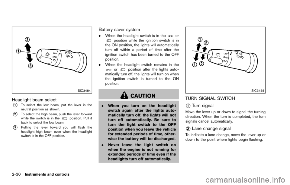
Headlight beam select
*1To select the low beam, put the lever in the
neutral position as shown.
*2To select the high beam, push the lever forward
while the switch is in theposition. Pull it
back to select the low beam.
*3Pulling the lever toward you will flash the
headlight high beam even when the headlight
switch is in the OFF position.
Battery saver system
. When the headlight switch is in theorposition while the ignition switch is in
the ON position, the lights will automatically
turn off within a period of time after the
ignition switch has been turned to the OFF
position.
. When the headlight switch remains in the
orposition after the lights auto-
matically turn off, the lights will turn on when
the ignition switch is turned to the ON
position.
CAUTION
. When you turn on the headlight
switch again after the lights auto-
matically turn off, the lights will not
turn off automatically. Be sure to
turn the light switch to the OFF
position when you leave the vehicle
for extended periods of time, other-
wise the battery will be discharged.
. Never leave the light switch on
when the engine is not running for
extended periods of time even if the
headlights turn off automatically.
SIC3488
TURN SIGNAL SWITCH
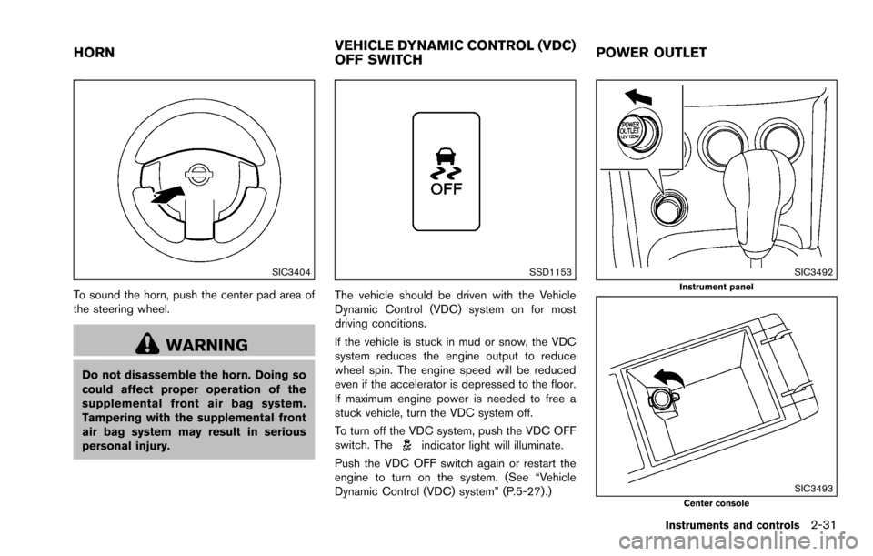
*1Turn signal
Move the lever up or down to signal the turning
direction. When the turn is completed, the turn
signals cancel automatically.
*2Lane change signal
To indicate a lane change, move the lever up or
down to the point where lights begin flashing.
Page 106 of 322
SIC3404
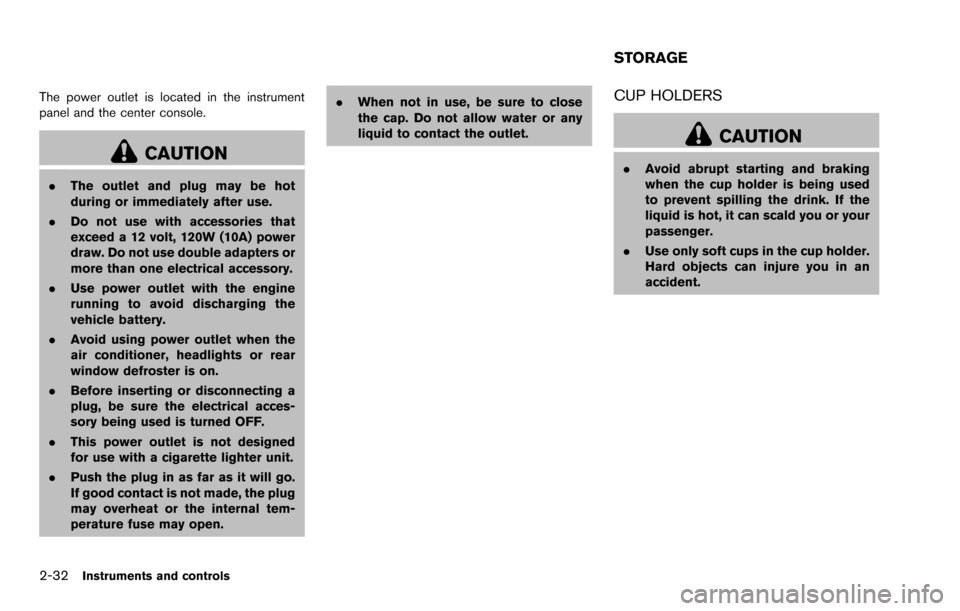
To sound the horn, push the center pad area of
the steering wheel.
WARNING
Do not disassemble the horn. Doing so
could affect proper operation of the
supplemental front air bag system.
Tampering with the supplemental front
air bag system may result in serious
personal injury.
SSD1153
The vehicle should be driven with the Vehicle
Dynamic Control (VDC) system on for most
driving conditions.
If the vehicle is stuck in mud or snow, the VDC
system reduces the engine output to reduce
wheel spin. The engine speed will be reduced
even if the accelerator is depressed to the floor.
If maximum engine power is needed to free a
stuck vehicle, turn the VDC system off.
To turn off the VDC system, push the VDC OFF
switch. The
indicator light will illuminate.
Push the VDC OFF switch again or restart the
engine to turn on the system. (See “Vehicle
Dynamic Control (VDC) system” (P.5-27) .)
SIC3492Instrument panel
SIC3493Center console
Instruments and controls2-31
HORN VEHICLE DYNAMIC CONTROL (VDC)
OFF SWITCHPOWER OUTLET
Page 107 of 322
2-32Instruments and controls
The power outlet is located in the instrument
panel and the center console.
CAUTION
.The outlet and plug may be hot
during or immediately after use.
. Do not use with accessories that
exceed a 12 volt, 120W (10A) power
draw. Do not use double adapters or
more than one electrical accessory.
. Use power outlet with the engine
running to avoid discharging the
vehicle battery.
. Avoid using power outlet when the
air conditioner, headlights or rear
window defroster is on.
. Before inserting or disconnecting a
plug, be sure the electrical acces-
sory being used is turned OFF.
. This power outlet is not designed
for use with a cigarette lighter unit.
. Push the plug in as far as it will go.
If good contact is not made, the plug
may overheat or the internal tem-
perature fuse may open. .
When not in use, be sure to close
the cap. Do not allow water or any
liquid to contact the outlet.
CUP HOLDERS
CAUTION
.Avoid abrupt starting and braking
when the cup holder is being used
to prevent spilling the drink. If the
liquid is hot, it can scald you or your
passenger.
. Use only soft cups in the cup holder.
Hard objects can injure you in an
accident.
STORAGE
Page 117 of 322
2-42Instruments and controls
CAUTION
Do not use for extended periods of time
with the engine stopped. This could
result in a discharged battery.
MAP LIGHTS
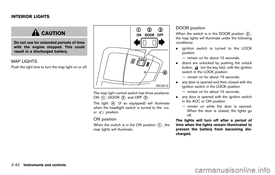
Push the light lens to turn the map light on or off.
SIC3512
The map light control switch has three positions:
ON
*1, DOOR*2and OFF*3.
The light
*4(if so equipped) will illuminate
when the headlight switch is turned to the
orposition.
ON position
When the switch is in the ON position*1, the
map lights will illuminate.
DOOR position
When the switch is in the DOOR position*2,
the map lights will illuminate under the following
conditions:
. ignition switch is turned to the LOCK
position
— remain on for about 15 seconds.
. doors are unlocked by pushing the unlock
button
(on the key fob) , with the ignition
switch in the LOCK position
— remain on for about 15 seconds.
. any door is opened and then closed with the
ignition switch in the LOCK position
— remain on for about 15 seconds.
. any door is opened with the ignition switch
in the ACC or ON position
— remain on while the door is opened.
When the door is closed, the lights go
off.
The lights will turn off after a period of
time when the lights remain illuminated to
prevent the battery from becoming dis-
charged.
INTERIOR LIGHTS