2015 NISSAN ROGUE SELECT display
[x] Cancel search: displayPage 98 of 322
3. Driving Distance (miles or km)
The Driving Distance mode shows the distance
driven since the last reset. The driving distance
can be reset by pushing and holding the
switch*Afor less than 3 seconds.
4. Elapsed Time
The Elapsed Time mode shows the time since
the last reset. The displayed time can be reset
by pushing and holding the
switch*Afor
less than 3 seconds.
5. Range (distance to empty) (dte —
miles or km)
The distance to empty (dte) mode provides you
with an estimation of the distance that can be
driven before refueling. The dte is constantly
being calculated based on the amount of fuel in
the fuel tank and the actual fuel consumption.
The display is updated every 30 seconds.
The dte mode includes a low range warning
feature. If the fuel level is low, the warning is
displayed on the screen.
When the fuel level drops even lower, the dte
display will change to “----”.
. If the amount of fuel added is small, the
display just before the ignition switch is
turned to the “OFF” position may continue to
be displayed. .
When driving uphill or rounding curves, the
fuel in the tank shifts, which may momenta-
rily change the display.
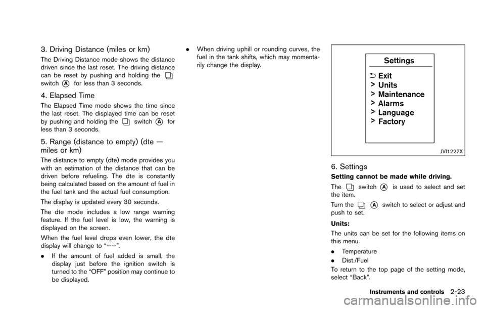
JVI1227X
6. Settings
Setting cannot be made while driving.
The
switch*Ais used to select and set
the item.
Turn the
*Aswitch to select or adjust and
push to set.
Units:
The units can be set for the following items on
this menu.
. Temperature
. Dist./Fuel
To return to the top page of the setting mode,
select “Back”.
Instruments and controls2-23
Page 99 of 322
2-24Instruments and controls
Maintenance:
The maintenance intervals of the following items
can be set or reset for the reminders.
.Service
Select this submenu to set or reset the
distance for service due.
. Tire
Select this submenu to set or reset the
distance for replacing tires.
. Other
Select this submenu and set or reset the
distance for items other than service or tires.
To return to the top page of the setting mode,
select “Back”.
Alarms:
Alarms menu can be set to notify the following
items.
. Driver alert
Select this submenu to set the driver alert
period.
. Outside temp
Select this submenu to turn ON or OFF the
low outside temperature warning features.
For a description of the low outside tem-
perature warning features when Outside
Temp is set to ON, see “Outside air
temperature” (P.2-17). With Outside Temp set to OFF,
— The outside temperature display remains
on steady at all outside temperatures and
does not flash.
— The low outside temperature warning indicator does not appear.
To return to the top page of the setting mode,
select “Back”.
Language:
Select the submenu to set the desired language
of the display.
Factory:
Select the submenu to reset the factory settings
of the display.
NOTE:
When resetting Factory, all previous set-
tings made are changed to default.
To return to the top page of the setting mode,
select “Back”.
CONTINUOUSLY VARIABLE TRANS-
MISSION (CVT) POSITION INDICATOR
The Continuously Variable Transmission (CVT)
position indicator indicates the shift lever posi-
tion when the ignition switch is in the ON
position.
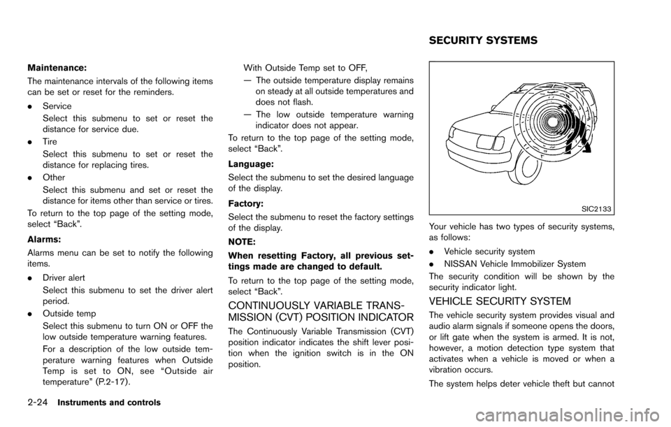
SIC2133
Your vehicle has two types of security systems,
as follows:
. Vehicle security system
. NISSAN Vehicle Immobilizer System
The security condition will be shown by the
security indicator light.
VEHICLE SECURITY SYSTEM
The vehicle security system provides visual and
audio alarm signals if someone opens the doors,
or lift gate when the system is armed. It is not,
however, a motion detection type system that
activates when a vehicle is moved or when a
vibration occurs.
The system helps deter vehicle theft but cannot
SECURITY SYSTEMS
Page 131 of 322
3-12Pre-driving checks and adjustments
.Do not fill a portable fuel container
in the vehicle or trailer. Static elec-
tricity can cause an explosion of
flammable liquid, vapor or gas in
any vehicle or trailer. To reduce the
risk of serious injury or death when
filling portable fuel containers:
— Always place the container on
the ground when filling.
— Do not use electronic devices when filling.
— Keep the pump nozzle in contact with the container while you are
filling it.
— Use only approved portable fuel containers for flammable liquid.
CAUTION
. If fuel is spilled on the vehicle body,
flush it away with water to avoid
paint damage.
. Insert the cap straight into the fuel-
filler tube, then tighten until the
fuel-filler cap clicks. Failure to tight-
en the fuel-filler cap properly may cause the
malfunction indicator
light (MIL) to illuminate. If the
light illuminates because the fuel-
filler cap is loose or missing, tighten
or install the cap and continue to
drive the vehicle. The
light
should turn off after a few driving
trips. If the
light does not turn
off after a few driving trips, have the
vehicle inspected by a NISSAN deal-
er.
For additional information, see
“Malfunction Indicator Light (MIL)”
(P.2-15) .
. The LOOSE FUEL CAP warning will
appear if the fuel-filler cap is not
properly tightened. It may take a few
driving trips for the message to be
displayed. Failure to tighten the
fuel-filler cap properly after the
LOOSE FUEL CAP warning appears
may cause the Malfunction Indicator
Light (MIL) to illuminate.
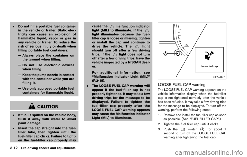
SPA2807
LOOSE FUEL CAP warning
The LOOSE FUEL CAP warning appears on the
vehicle information display when the fuel-filler
cap is not tightened correctly after the vehicle
has been refueled. It may take a few driving trips
for the message to be displayed. To turn off the
warning, perform the following steps:
1. Remove and install the fuel-filler cap as soon
as possible. (See “FUEL-FILLER CAP”.)
2. Tighten the fuel-filler cap until it clicks.
3. Push the
switch*Afor about 1
second to turn off the LOOSE FUEL CAP
warning after tightening the fuel cap.
Page 136 of 322
4 Heater, air conditioner, audio, phone and voicerecognition systems
Safety note ........................................................................\
.......... 4-2
RearView Monitor (if so equipped) ...................................... 4-2
How to read the displayed lines ..................................... 4-3
Difference between predictive and
actual distances ................................................................... 4-3
How to adjust the screen ................................................. 4-6
Operating tips ...................................................................... 4-6
Ventilators ........................................................................\
............ 4-7
Heater and air conditioner ...................................................... 4-8 Manual air conditioner ........................................................ 4-9
In-cabin microfilter ........................................................... 4-11
Servicing air conditioner ................................................. 4-11
Audio system ........................................................................\
... 4-12
Audio operation precautions ......................................... 4-12
FM-AM radio with Compact Disc (CD) player ......... 4-22
FM-AM-SAT radio with Compact Disc
(CD) player ........................................................................\
4-29 CD/DVD/USB memory care and cleaning .............. 4-37
Steering wheel switch for audio control (if
so equipped) ................................................................... 4-37
Antenna ........................................................................\
.... 4-38
Car phone and CB radio .................................................... 4-39
Bluetooth
�ŠHands-Free Phone System (if
so equipped) ........................................................................\
.. 4-40
Regulatory information .................................................. 4-41
Using the system ........................................................... 4-41
Control buttons ............................................................... 4-43
Getting started ............................................................... 4-44
List of voice commands ............................................... 4-45
Speaker Adaptation (SA) mode ................................. 4-49
Troubleshooting guide .................................................. 4-51
Page 137 of 322
4-2Heater, air conditioner, audio, phone and voice recognition systems
WARNING
.Do not disassemble or modify this
system. If you do, it may result in
accidents, fire, or electric shock.
. Do not use this system if you notice
any abnormality, such as a frozen
screen or lack of sound. Continued
use of the system may result in
accident, fire or electric shock.
. In case you notice any foreign
object in the system hardware, spill
liquid on it, or notice smoke or smell
coming from it, stop using the
system immediately and contact
your nearest NISSAN dealer. Ignor-
ing such conditions may lead to
accidents, fire, or electric shock.
Do not attempt to operate the system in
extreme temperature conditions [below
�í 48F( �í208 C) and above 1588 F (708C)].
Operating this system under these condi-
tions may result in system malfunctions. The system is designed as an aid to the driver in
situations such as slot parking or parallel
parking.
When the shift lever is shifted into the R
(Reverse) position, the monitor display shows
the view to the rear of the vehicle.
WARNING
Failure to follow the warnings and
instructions for proper use of the Rear-
View Monitor could result in serious
injury or death.
.
The RearView Monitor is a conve-
nience but it is not a substitute for
proper backing. Always turn and
look out the windows, and check
mirrors to be sure that it is safe to
move before operating the vehicle.
Always back up slowly.
. The system is designed as an aid to
the driver in showing large station-
ary objects directly behind the vehi-
cle, to help avoid damaging the
vehicle.
. The system cannot completely elim-
inate blind spots and may not show
every object. .
Underneath the bumper and the
corner areas of the bumper cannot
be viewed on the RearView Monitor
because of its monitoring range
limitation. The system will not show
small objects below the bumper,
and may not show objects close to
the bumper or on the ground.
. Objects viewed in the RearView
Monitor differ from actual distance
because a wide-angle lens is used.
. Objects in the RearView Monitor
will appear visually opposite than
when viewed in the rearview and
outside mirrors.
. Make sure that the lift gate is
securely closed when backing up.
. Do not put anything on the rear view
camera.
. When washing the vehicle with
high-pressure water, be sure not to
spray it around the camera. Other-
wise, water may enter the camera
unit causing water condensation on
the lens, a malfunction, fire or an
electric shock.
. Do not strike the camera. It is a
precision instrument. Otherwise, it
SAFETY NOTE REARVIEW MONITOR (if so
equipped)
Page 138 of 322
may malfunction or cause damage
resulting in a fire or an electric
shock.
CAUTION
Do not scratch the camera lens when
cleaning dirt or snow from the lens.
SAA2776
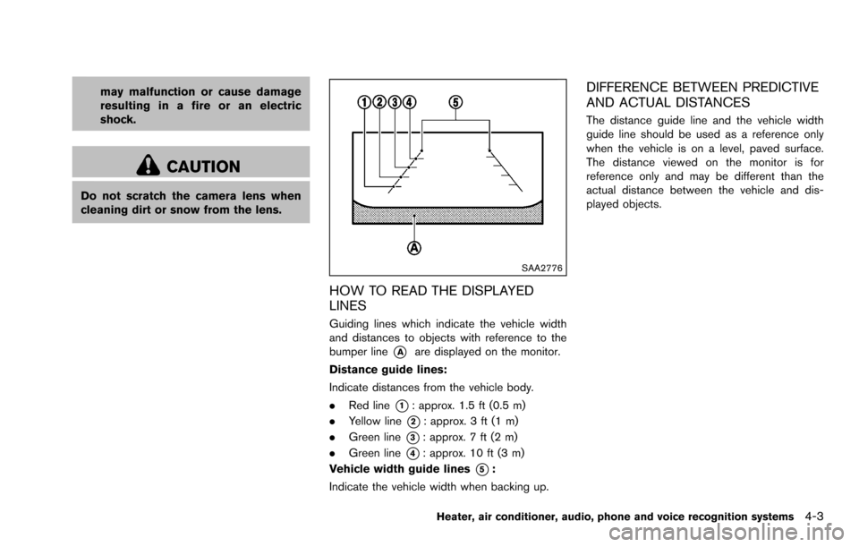
HOW TO READ THE DISPLAYED
LINES
Guiding lines which indicate the vehicle width
and distances to objects with reference to the
bumper line
*Aare displayed on the monitor.
Distance guide lines:
Indicate distances from the vehicle body.
. Red line
*1: approx. 1.5 ft (0.5 m)
. Yellow line
*2: approx. 3 ft (1 m)
. Green line
*3: approx. 7 ft (2 m)
. Green line
*4: approx. 10 ft (3 m)
Vehicle width guide lines
*5:
Indicate the vehicle width when backing up.
DIFFERENCE BETWEEN PREDICTIVE
AND ACTUAL DISTANCES
The distance guide line and the vehicle width
guide line should be used as a reference only
when the vehicle is on a level, paved surface.
The distance viewed on the monitor is for
reference only and may be different than the
actual distance between the vehicle and dis-
played objects.
Heater, air conditioner, audio, phone and voice recognition systems4-3
Page 139 of 322
4-4Heater, air conditioner, audio, phone and voice recognition systems
SAA1978
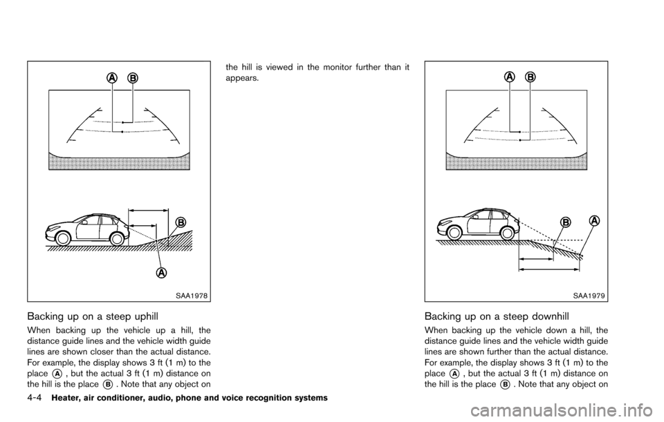
Backing up on a steep uphill
When backing up the vehicle up a hill, the
distance guide lines and the vehicle width guide
lines are shown closer than the actual distance.
For example, the display shows 3 ft (1 m) to the
place
*A, but the actual 3 ft (1 m) distance on
the hill is the place
*B. Note that any object on the hill is viewed in the monitor further than it
appears.
SAA1979
Backing up on a steep downhill
When backing up the vehicle down a hill, the
distance guide lines and the vehicle width guide
lines are shown further than the actual distance.
For example, the display shows 3 ft (1 m) to the
place
*A, but the actual 3 ft (1 m) distance on
the hill is the place
*B. Note that any object on
Page 140 of 322
the hill is viewed in the monitor closer than it
appears.
SAA3440
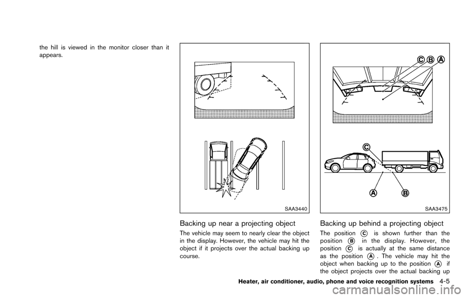
Backing up near a projecting object
The vehicle may seem to nearly clear the object
in the display. However, the vehicle may hit the
object if it projects over the actual backing up
course.
SAA3475
Backing up behind a projecting object
The position*Cis shown further than the
position
*Bin the display. However, the
position
*Cis actually at the same distance
as the position
*A. The vehicle may hit the
object when backing up to the position
*Aif
the object projects over the actual backing up
Heater, air conditioner, audio, phone and voice recognition systems4-5