Page 363 of 440
QR25DE engine
1. Engine coolant reservoir
2. Engine oil filler cap
3. Brake fluid reservoir
4. Battery
5. Air cleaner
6. Fuse/Fusible link box
7. Radiator cap
8. Engine oil dipstick
9. Drive belt location
10. Windshield-washer fluid reservoir
* Engine cover removed for clarity.
LDI2434
ENGINE COMPARTMENT CHECK
LOCATIONS
8-6Maintenance and do-it-yourself
Page 371 of 440

●Keep the battery surface clean and dry.
Clean the battery with a solution of baking
soda and water.
● Make certain the terminal connections are
clean and securely tightened.
● If the vehicle is not to be used for 30 days or
longer, disconnect the negative (-) battery
terminal cable to prevent discharge.
NOTE:
Care should be taken to avoid situations
that can lead to potential battery discharge
and potential no-start conditions such as: 1. Installation or extended use of electronic accessories that consume battery power
when the engine is not running (Phone char-
gers, GPS, DVD players, etc.)
2. Vehicle is not driven regularly and/or only driven short distances. In these cases, the
battery may need to be charged to maintain
battery health.WARNING
●Do not expose the battery to flames, an
electrical spark or a cigarette. Hydrogen
gas generated by the battery is explo-
sive. Explosive gases can cause blind-
ness or injury. Do not allow battery fluid
to contact your skin, eyes, fabrics or
painted surfaces. Sulfuric acid can
cause blindness or injury. After touch-
ing a battery or battery cap, do not
touch or rub your eyes. Thoroughly
wash your hands. If the acid contacts
your eyes, skin or clothing, immediately
flush with water for at least 15 minutes
and seek medical attention.
● Do not operate the vehicle if the fluid in
the battery is low. Low battery fluid can
cause a higher load on the battery
which can generate heat, reduce battery
life, and in some cases lead to an
explosion.
● When working on or near a battery, al-
ways wear suitable eye protection and
remove all jewelry.
● Battery posts, terminals and related ac-
cessories contain lead and lead com-
pounds. Wash hands after handling. ●
Keep battery out of the reach of
children.
● Do not tip the battery. Keep the vent
caps tight and the battery level.
BATTERY
8-14Maintenance and do-it-yourself
Page 372 of 440
1. Remove the vent caps with a screwdriver asshown. Use a cloth to protect the battery
case.
2. Check the fluid level in each cell. If it isnecessary to add fluid, add only distilled
water to bring the level up to the bottom of
the filler opening. Do not overfill.Reinstall
the vent caps. Vehicles operated in high temperatures or under
severe conditions require frequent checks of the
battery fluid level.
Battery (Type A) (if so equipped)
WDI0224
LDI0302
Maintenance and do-it-yourself8-15
Page 373 of 440

The Type B battery is not equipped with remov-
able vent caps. If low battery fluid is suspected,
see a NISSAN dealer.
JUMP STARTING
If jump starting is necessary, refer to “Jump start-
ing” in the “In case of emergency” section of this
manual. If the engine does not start by jump
starting, the battery may have to be replaced.
Contact a NISSAN dealer.
1. Crankshaft pulley
2. Drive belt automatic tensioner pulley
3. Water pump pulley
4. Generator pulley
5. Air conditioner pulley
WARNING
Be sure the ignition switch is placed in the
OFF or LOCK position before servicing
drive belt. The engine could rotate
unexpectedly.1. Visually inspect the belt for signs of unusual
wear, cuts, fraying or looseness. If the belt is
in poor condition or is loose, have it replaced
or adjusted by a NISSAN dealer.
2. Have the belt checked regularly for condi- tion and tension in accordance with the
maintenance schedule found in the
“NISSAN Service and Maintenance Guide”.
Battery (Type B) (if so equipped)
LDI2817
QR25DE engine
LDI2130
DRIVE BELT
8-16Maintenance and do-it-yourself
Page 381 of 440
Extended storage switch
If any electrical equipment does not operate,
remove the extended storage switch and check
for an open fuse.
NOTE:
The extended storage switch is used for
long term vehicle storage. Even if the ex-
tended storage switch is broken it is not
necessary to replace it. Replace only the
open fuse in the switch with a new fuse.How to replace the extended storage switch:
1. To remove the extended storage switch, be sure the ignition switch is in the OFF or
LOCK position.
2. Be sure the headlight switch is in the OFF position.
3. Remove the fuse box cover.
4. Pinch the locking tabs
�1found on each
side of the storage switch.
5. Pull the storage switch straight out from the fuse box
�2.
CAUTION
Be careful not to allow children to swallow
the battery or removed parts.
LDI2350
BATTERY REPLACEMENT
8-24Maintenance and do-it-yourself
Page 382 of 440
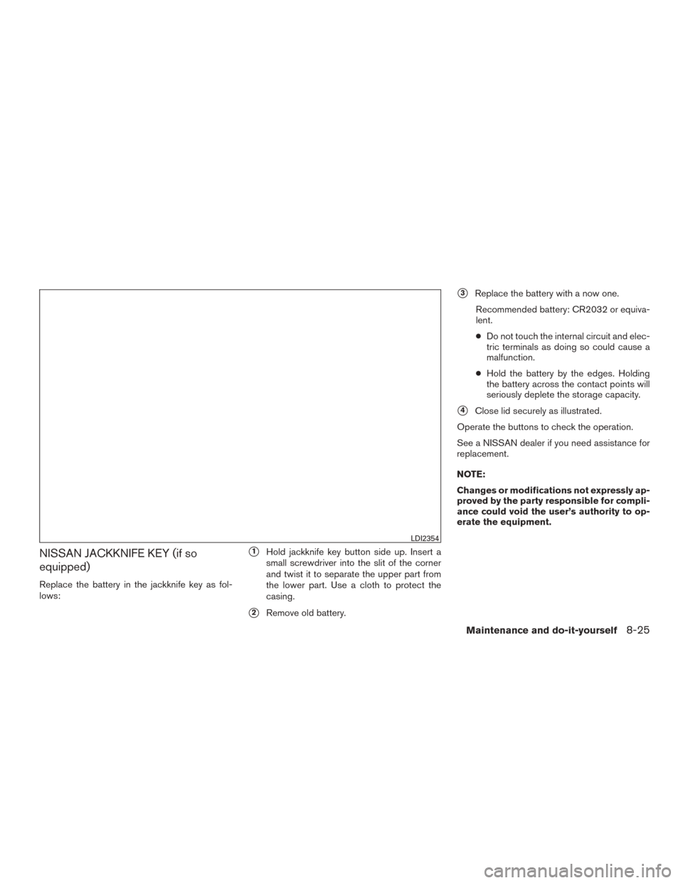
NISSAN JACKKNIFE KEY (if so
equipped)
Replace the battery in the jackknife key as fol-
lows:
�1Hold jackknife key button side up. Insert a
small screwdriver into the slit of the corner
and twist it to separate the upper part from
the lower part. Use a cloth to protect the
casing.
�2Remove old battery.
�3Replace the battery with a now one.
Recommended battery: CR2032 or equiva-
lent.
● Do not touch the internal circuit and elec-
tric terminals as doing so could cause a
malfunction.
● Hold the battery by the edges. Holding
the battery across the contact points will
seriously deplete the storage capacity.
�4Close lid securely as illustrated.
Operate the buttons to check the operation.
See a NISSAN dealer if you need assistance for
replacement.
NOTE:
Changes or modifications not expressly ap-
proved by the party responsible for compli-
ance could void the user’s authority to op-
erate the equipment.
LDI2354
Maintenance and do-it-yourself8-25
Page 383 of 440
 This device may
not cause harmful interference, and (2) this
device")
FCC Notice:
For USA:
This device complies with Part 15 of the
FCC Rules. Operation is subject to the fol-
lowing two conditions: (1) This device may
not cause harmful interference, and (2) this
device must accept any interference re-
ceived, including interference that may
cause undesired operation.
Note: Changes or modifications not ex-
pressly approved by the party responsible
for compliance could void the user’s au-
thority to operate the equipment.
For Canada:
This device complies with Industry Canada
licence-exempt RSS standard(s) . Opera-
tion is subject to the following two condi-
tions: (1) this device may not cause inter-
ference, and (2) this device must accept any
interference, including interference that
may cause undesired operation of the de-
vice.NISSAN INTELLIGENT KEY® (if so
equipped)
Replace the battery in the Intelligent Key as fol-
lows:1. Remove the mechanical key from the Intelli- gent Key.
2. Insert a small screwdriver
�Ainto the slit�B
of the corner and twist it to separate the
upper part from the lower part. Use a cloth to
protect the casing.
3. Replace the battery with a new one. Recommended battery: CR2025 or equiva-
lent.
●Do not touch the internal circuit and elec-
tric terminals as doing so could cause a
malfunction.
● Hold the battery by the edges. Holding
the battery across the contact points will
seriously deplete the storage capacity.
● Make sure that the + side faces the bot-
tom of the case.
SDI1867
8-26Maintenance and do-it-yourself
Page 424 of 440
 can be used to tow trailers
of a maximum weight of 2,000 lb (907 kg) .
Tire pressures
●When towing a trailer, infl")
Class I hitch
Class I trailer hitch equipment (receiver, ball
mount and hitch ball) can be used to tow trailers
of a maximum weight of 2,000 lb (907 kg) .
Tire pressures
●When towing a trailer, inflate the ve-
hicle tires to the recommended cold
tire pressure indicated on the Tire
and Loading Information label.
● Trailer tire condition, size, load rating
and proper inflation pressure should
be in accordance with the trailer and
tire manufacturer’s specifications.
Safety chains
Always use suitable safety chains between your
vehicle and the trailer. The safety chains should
be crossed and should be attached to the hitch,
not to the vehicle bumper or axle. The safety
chains can be attached to the bumper if the hitch
ball is mounted to the bumper. Be sure to leave
enough slack in the chains to permit turning
corners.
Trailer lights
CAUTION
When splicing into the vehicle electrical
system, a commercially available power-
type module/converter must be used to
provide power for all trailer lighting. This
unit uses the vehicle battery as a direct
power source for all trailer lights while
using the vehicle tail light, stoplight and
turn signal circuits as a signal source. The
module/converter must draw no more that
15 milliamps from the stop and tail lamp
circuits. Using a module/converter that
exceeds these power requirements may
damage the vehicle’s electrical system.
See a reputable trailer retailer to obtain
the proper equipment and to have it
installed.
Trailer lights should comply with federal and/or
local regulations. For assistance in hooking up
trailer lights, contact a NISSAN dealer or repu-
table trailer retailer. Vehicles equipped with the
optional trailer tow package are equipped with a
7-pin trailer harness connector. If your trailer is
equipped with a flat 4-pin connector, an adapter
will be needed to connect the trailer lights to the
vehicle. Adapters are available at auto parts
stores and hitch retailers.
Pre-towing tips
● Be certain your vehicle maintains a level
position when a loaded and/or unloaded
trailer is hitched. Do not drive the vehicle if it
has an abnormal nose-up or nose-down
condition; check for improper tongue load,
overload, worn suspension or other possible
causes of either condition.
● Always secure items in the trailer to prevent
load shift while driving.
● Keep the cargo load as low as possible in
the trailer to keep the trailer center of gravity
low.
● Load the trailer so approximately 60% of the
trailer load is in the front half and 40% is in
the back half. Also make sure the load is
balanced side to side.
● Check your hitch, trailer tire pressure, ve-
hicle tire pressure, trailer light operation, and
trailer wheel lug nuts every time you attach a
trailer to the vehicle.
● Be certain your rearview mirrors conform to
all federal, state or local regulations. If not,
install any mirrors required for towing before
driving the vehicle.
Technical and consumer information9-23